I thought it would be cool to utilize the front narrow T-badge support area on the Model S for a light show. This project could be adapted to other places for older cars or the Model X/3/Y. It could also be greatly simplified if you wanted a single color, or simply use an RGB strip. I’ll leave that for another owner! The Tshow project uses a small processor to control the individual LED pixel colors across a strip of closely spaced 88 quad-LEDs, or 352 LEDs in total. The system connects to the car to automatically change the visual styles under various conditions such as driving, parked, or showing the charging level. If not using the default operations, you can override styles, colors, brightness, and much more via an optional Android app using Bluetooth. (May-2022 update)
Video – Typical operations – charging, parked, and driving states. See part 10 for a short video with many more modes and colors.
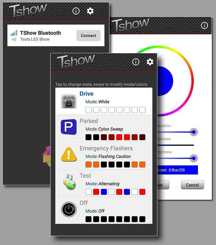
Control via the Tshow app
This large project is broken up into many sections:
| Part 1 | Overview – This covers the summary, features, costs, warranty concerns, legalities, power requirements, and NeoPixels. | |
| Part 2 | Processor Module – The 32-bit microcontroller, CAN bus interfaces, DC/DC inverter, Bluetooth, level translators, and some additional circuitry are all within the processor module. It’s the hub of the project. | |
| Part 3 | Receiver Module – This is a small unit that converts a differential signal from the processor module to a binary signal that the LEDs can accept. It allows the signal to go over longer distances (16 feet or so). | |
| Part 4 | Front LED Assembly – This is the black plastic 30” wide indent behind the Tesla T-badge on the refreshed Model S. This holds a strip of addressable LEDs. It is covered with translucent plastic. | |
| Part 5 | Remote Module – When you’re in the car, you can’t see what the front is doing, so I created a tiny module that shows a mini-view of the front LEDs using 5 LEDs. We included a state button so it’s easy to override the current visual state. | |
| Part 6 | Testing – With a project this complex, it’s wise to test out the system before installing it. | |
| Part 7 | Using the Phone App – The ultimate remote control! | |
| Part 8 | Installation – Installing the various modules and assemblies, along with making various connecting cables. | |
| Part 9 | Designing Tshow – How I created Tshow along with schematics. | |
| Part 10 | Conclusion – My final thoughts and a demo video! |
Tshow has 5 states controlled by the car, the manual override button, or the app
- Driving – When the car is not in park – The default is white
- Parked – Default is red “Cylon” mode that sweeps back and forth (low power)
- Emergency – When the emergency flashers are active – the default is left/right amber synchronized flashing
- Test – Set by the app – can try out any mode
- Off – (very low power mode)
Visual styles available for most states:
- Alternating colors (like a string of Christmas lights)*
- Backlight (four center pixels)*
- Cylon sweep*
- Eyes, sweeping (moves back and forth)*
- Eyes, steering (follows the steering angle)*
- Fast Flashing Caution
- Fast Flashing Red/Blue Police (for police officers only)
- Fast Flashing Select (any two colors)*
- Gradient Center (two colors)*
- Rainbow
- Single Color*
- Sliding Colors
- Sliding colors from Center
- Test Charging (simulates car charging)
- Test Holidays (rotates through all holiday modes)
- Test LEDs (rotates through all white, red, green, and blue)
- Test Status (show internal statuses such as Bluetooth connection and the current date and time in binary)
- White
- Off
* Colors can be customized for the mode along with intensity level
Some states offer to override options for special car conditions:
- Synchronized blinkers – flashes amber left/right synchronized with the blinkers
- Charging cord connected – shows the current SOC from 0 to 100% in blue
- Charging – shows the current SOC from 0 to 100% in green with a “charging” animation
- Holidays – change to a preset special style for each holiday on the day of the holiday. Holidays include New Years, Valentines, St. Patrick’s, Easter, Cinco de Mayo, Flag, Independence, Halloween, Thanksgiving, Christmas, and New Year’s Eve.
Other features include
- Automatic brightness, based on headlights on/off and the time of dusk/dawn for each day (auto-adjusted throughout the year at about 37 degrees Latitude (San Jose, CA; Virginia Beach, VA; Seoul, South Korea). Dimmer levels can be adjusted from the app.
- Dimmer timeout – After 8 hours in park, the LEDs will dim to conserve power. This timeout is also changeable by the app.
- Off Timeout – After 36 hours in park, Tshow will turn off. This timeout is also changeable by the app.
- Hard Remote Option – For the interior of the car, a tiny 5 LED module shows a mini-view of what appears on the front display. A state change button rotates through each state, and auto-resumes when any of the 3 car state changes (Drive/Park/Emergency).
- OLED Micro Display Option – shows detected Tshow states via CAN; SOC; battery temperature percent; main and 12v battery voltage, current and power; date and time; and a graph of the last 90 seconds of main power usage and regen.
This is a very complex project, and I do not explain every tiny detail. I really don’t expect anyone to build this as the cost and effort probably exceed the value. I did go ahead and document much of the project, should someone be nutty enough to consider replicating it. I spent more than $1000 on the various parts, with some unnecessary, duplicates and those that ended up trashed due to design improvements and changes. With the final design, it would cost about $450 in raw parts, at a volume level of one. At higher volumes, the cost could come down.
You should have a good assortment of tools, some power tools like a table saw and electronic tools such as a quality soldering iron. You should have a good understanding of electronics (at least to assemble the 3 PCBs), and excellent mechanical skills. You may need Java and C++ software skills and assorted tools such as Android Studio and the Arduino IDE. You’ll also need to make several 3D boxes, which there are plenty of third parties that can print cheaply. Lastly, you should have good automotive skills, as you’ll be pulling apart your car, routing wires, and doing other tasks.
I can’t estimate how much time it will take, as I spent over 10 months (part-time) designing the circuitry, writing the code, prototyping, testing, creating schematics and PCBs, creating 3D boxes, assembling, and mundane tasks like this writeup! I’ve also spent another couple of months in 2022 with a second design to support the CAN bus from the 3/Y and Model S/X 2021+ LR/Plaid. Obviously, it should take you a fraction of that time. The skill level you bring to the project will have the largest factor in how fast it goes. While the optional Tesla parts took less than a week to obtain, some non-Tesla parts took over 2 months to get, due to unexpected issues. If a kit of pre-assembled parts were available, I suspect it would take about 4 hours to install in the Tesla, for someone already familiar with pulling the car apart to route wires.
From this point onward, I will call out differences between the Tshow design and installation for the refreshed Model S manufactured between June 2016 and December 2020 which the project was originally done as “Refresh” and the Model S LR/Plaid manufactured from February 2021 and later will be referred to as “Plaid”.
If you are interested in manufacturing a kit or assembled system for others (even for profit), contact me. I’ve done much of the complex engineering work, but am not interested in making sales myself.
Gradient center – colors green to blue
I try to make as little of an impact on the car and go out of my way to avoid making holes or cuts to the car. This project does require extensive modification to the front T-badge assembly, but it is only $40 in Tesla parts. We also make one hole in a grommet to pass wires into the cabin. Lastly, we drill one or two holes in the center console that is not visible for the remote cable. You could elect to place the remote in another spot that may not require holes.
Like all our projects, so long as you don’t break something else, the system should not affect your warranty. I’m not going to take any responsibility for things going wrong or something you break while working on your car! In ten years of various Tesla projects, I have yet to break something (although we did dent a trim piece years ago when I dropped my camera!).
I also designed the project so it would not interfere with Tesla’s normal maintenance. Everything is connectorized to make it trivial to gain access or repair something nearby.
Tshow can display colors that may be illegal in your state or country. I take no responsibility for any colors or animations that may be illegal in your jurisdiction.
For example, in the USA, while driving, only white or amber illumination in front of a vehicle is legal. Unless you are qualified emergency personnel, such as a police officer on duty, you cannot display the police red/blue fast alternating flashers on a public road at any time. There could be other limitations.
The power will vary depending on the number of pixels lit, colors used, brightness level, and other factors. While it might be possible to pull up to 1-2 amps (Every LED pixel full-on with all four colors on), the defaults keep the power levels to below 500 mA, about the level of many Dashcams. This assumes a string of 88 LEDs and 5 remote monitor LEDs. Current drawn from the car (12v) at the bright daytime level:
Off – 42 mA (CPU/Bluetooth still running)
Low power “Background T” choice, with one color, 4 pixels – 130 mA
Cylon animation (single color) – 135 mA
One color, all LEDs on (Red, Green or Blue) – 310 mA
White – 485 mA
All LEDs (RGBW) – 1030 mA
Each pixel takes about 0.5 mA when off to power its internal circuitry so that it takes about 55 mA even if the entire string is dark. I added additional hardware to disconnect the pixel power if all pixels are set off to further conserve power.
The amount of power, even if left on maximum brightness for an extended period, will have little effect to range. Tshow will take much less than 50 W per day for the Cylon animation. If your car had no other power drains and no internal battery leakage, Tshow would run for 5 years!
NeoPixels is a brand name given to a strip of LEDs, where each LED is individually addressable, using a serial data line. Each Pixel has an input and output and the strip has each LED connected to the next. They are powered by 5 volts DC. Each pixel holds 4 LEDs – red, green, blue, and white. Actually, the white is a blue LED with a white phosphor cap that lights up white. The driver within the pixel can set any of 256 brightness levels for each sub-LEDs, to produce a wide range of colors.
A processor can command the connected string of LEDs to display a mix of colors and brightness. The processor can do this quickly enough that simple animations can be created.
The NeoPixel strip is sheathed in a transparent silicone cover, to keep moisture and dirt out.
20 comments
I got e-mailed notification that this project has been updated for use with the Plaid S also, and maybe the 3/Y/X, but maybe I am missing it. How?
The CAN codes have completely changed from the old S to the new Model LR/Plaid S/X for Tshow. These new CAN codes look to be similar to the 3/Y and are likely the same. Both the old and new CAN codes are documented in our article. In addition, the installation is different in the new Model S, which we go into detail along with new photos and part numbers. We created a new 3D printed box, which is thinner and easier to produce than the hand-modified box we used in the original project. We also added an OLED display option and an OBD-II connector. We don’t really expect anyone to duplicate the project, but it can give people ideas for their own projects.
Wow what an awesome project!!!
Do you think this may now be easier using an Arduino, maybe just using an app to control it rather than integrating into the CANBUS?
I have seen WS2815 LEDs these run direct off 12v.
Is it possible to detect some state changes from voltage pick ups or drops from places in the Frunk so everything could be integrated in there?
I can’t believe no one has properly commercialised this yet it is awesome. Congratulations on your hard work.
Glad you like it! I’m sure the project could be simplified. The CAN bus was needed to be legal (i.e. change to white when driving), but you could control it manually. You could also get rid of the Bluetooth and use a button for different modes. You really don’t want to use 12v LEDs – the vehicle’s 12v varies up to 14.5v or so. Better to have a DC-DC inverter as I used. You’ll likely need 5v anyway for the processor and other electronics. Arduino should be workable too. I picked the processor as it was cheap, low-power, small, and had two can bus connections. I leave it powered up all the time, but cut the display after 36 hours or so. It’s not that much of a drain, but figured it is better should the car is parked for an extended period. As for control on/off, perhaps you can find a line/fuse that you can detect when the car is powered down, and only then show the display. I’ve never looked into it. Good luck if you make one – it was a fun project!
Did anyone ever decide to take this project on to build units we can buy? It has been a very long time since I have done any soldering but I do love this project and really want to do it to my car.
A couple of people told me they wanted to commercialize it a while back, but so far nothing has come to fruition yet. I love the project, but it’s hard to get the costs low enough to make a business out of it.
I was wondering if you could mount a controller near the front. Something like a Raspberry Pi 0. This would keep you from having to route wires into the cabin. We would still need a 12v to 5 volt conversion, and then set it up to do bluetooth into the remote. I am considering doing this with Dotstar (similar to Neopixels) and the Pi just to see if I can 🙂
Great project, I’d be interested in your thoughts on availability of 12v near the frunk.
I haven’t checked, but I’m sure there are plenty of 12v sources in the frunk area. You have fuse box and the battery. Be sure to fuse your connection, but otherwise I’m sure it’s easy to find a good connection point. Getting to the CAN buses (if needed) should be possible too, but a bit more hunting to find the right connection. Before commiting, I’d try some kind of bluetooth test, as the frunk area is surrounded by metal and may inhibit connection to a phone. Good luck with your project!
Thanks, ya, my thought process was I could actually do a multi controller setup. A raspberry pi zero-w in the frunk area, and then have it networked to a raspberry pi 0 or 3 in the cabin to connect to the can bus. The PI3 would only tell the PIZero what to do, i.e. the thing processing the can data would basically send API requests to the PiZero to do LED things. This would also give me the ability to add a small speaker perhaps in the frunk area that I could do sound effects.
(I’ve always wanted to do make vroom vroom sounds when people in ICE cars VROOM VROOM at me) (And then when I accelerate, I would like the Jetson’s car sound)
It would be a bit “more” things that could go wrong, however, I wouldn’t be doing any connecting through the firewall. The rasp pi 0 will be in a more failure prone location(heat/cold etc), but they are also cheap, and if designed right, I could manage that. I will report back as I dig through more design.
This is amazing! The craftmanship is top-notch. I have a pre-refresh car so I can’t implement it, but it gives me some ideas and techniques for other projects. Bravo, and thank you.
More puzzles!
The standard OBD II connector has 16 pins, with CAN Hi on 6 and CAN Lo on 14. Your diagram in ‘8 – Installation’ mentions a 20 pin blue (New style) connector with GND on 20 and CAN 3 – on 19 and + on 18.
Your parts list includes “1 – Tesla Sept-2015+ Diagnostics connector with ribbon cable (or similar)”. Sod’s law, my car is late 2014 (with AP1). Any idea what that connector is?
In Tesla Motors Club there’s a picture of a late 2014 85S (same as mine) with a c. 16 pin white connector. Any idea where I could find the pin-out?
I can try just counting the holes in my connector but am wary of shorting something if I try to detect the voltages, and heaven knows how you find which CAN BUS you’ve detected!
Don’t use the ODB connector for CAN bus connections – you need to use he diagnostics connector above the cubby. There are two styles with different pinouts. I’ve updated the article with sources and pinouts for both old and new diagnostics connectors in Part 8.
I am struggling to find the CAN BUS connector. You mention that under the 17″ display is a cubby hole in plastic. I have found a narrow-ish one just under the screen and above the long black plastic ‘tray’ which runs back to the 12V outlet (for storing odds and ends), but on pressing down on the cubby hole moderately hard it doesn’t move. I am frightened of pushing harder in case I break a completely different part! I have taken a photo, but can’t find a way to include it. Any chance of an email or mobile number link?
There are two snaps at the top of the cubby. They are quite tight, but a strong pressure on the bottom of the cubby downward will release the snaps. I agree it requires quite a bit of pressure as do most snaps Tesla uses to release. There have been a couple of snaps elsewhere in the dashboard on my prior S that I could never get to release, but I’ve never broken any of the parts, and I’ve taken quite a few areas apart. The snaps are strong to prevent rattles and purposely make it hard for parts to come off under the vibration and pressures the car undergoes in everyday operation.
Here’s a open cubby picture (from someone else) where you can see the two snaps and access to the diagnostics connector.
Great thanks. I’ll take a deep breath and push harder!!
Does the TESLA CAN BUS communicate 500 (just to save me messing around with speeds!!)?
PS how did you insert the link to a picture?
The different CAN buses use different speeds. I documented it here: https://teslatap.com/undocumented/ about 1/4 of the way down.
As for picture or link, just add the link and it should work. You can also use the “link” button above the edit box (although it might be an admin only option).
PPS Do you happen to know the code for Charging Current?
Also you mention the massive amount of data on the Tesla CAN buses, and say your project does the code filtering in hardware. With an Arduino Uno and SKPand CAN shield, if just looping to test IF {message id =(say) Charge %}, would it keep up?
If not, does it just lose some data (not important to me) or does it crash something?
A loop as you suggest will likely fail – the data is just too much for most microprocessors to process. You will miss most of the data of interest, although I don’t think it will crash. Most CAN bus interface chips have a hardware method to watch only a specific CAN port id. You’ll really need to do this, although it’s more work to set up. Here are several links that may help (although it’s for the CAN library I used for the Teensy):
https://github.com/collin80/FlexCAN_Library
https://forum.pjrc.com/index.php?threads/another-fork-of-flexcan.39867/page-4
Your chips and programming is likely different for a CAN shield, so I don’t know what options they have to monitor a specific CAN id. I bet there are some good examples for your shield out there.
Thanks so much for that help – I’ll look into it all.
Too cool!
Complex project-creative, well thought-out. Excellent execution. Shows an abundance of imagination, knowledge,and talent.