2 – Waterproof connectorized cables, 6 foot, with stubs, or 12-foot cable soldered as needed; 4-wire, 18 gauge,
1 – Cable, 8 foot, 6-conductor, 22 gauge, stranded
1 – RJ12 Phone cord, 6-conductor, 28 gauge, stranded, preferably black
2 – RJ12 6P6C crimp plugs (requires special crimping tool)
1 – Molex mating 12-pin Female connector #34729-0121
6 – Molex female crimp terminals #34803-3212 (sold in a string of 100)
2 – Male/Female 6-pin 10 amp Auto Connectors (comes in a kit of 5 pairs)
4 – Wires, 22 gauge, stranded, 1-2” long each
1 – Epoxy – two-part, for metal to plastic (also used in the prior section)
6 – Magnets – 10mm diameter x 1mm thick (ordered in prior section as a set of 25)
4 – Tie wraps as needed
2 – Adhesive tie wrap pads
For Tesla X or S Sept 2015+
1 – Diagnostics connector with ribbon cable (or similar). We no longer have a source for this part.
For Tesla S before Sept 2015
1 – TE Connectivity Data Connector Mfg Part#173851-2
12 – TE Connectivity Connector Pins Mfg Part#173630-6
You really want to install the Tshow processor module in the cabin. It’s a better environmental area than outside the cabin. Originally, I planned to install it in the inside front part of the center console, where it fits nicely. This is a rather hard place to get to, and it may need to be removed to update the software. My first car didn’t have the pano roof or air suspension modules, so those areas were considered, but both are difficult to get to, and may not have enough free space for the Tshow processor module. I finally found a good place under the passenger seat. Easy to access and a good location to run wires. The 3D printed black box (shown below) is thinner and works even better under the seat. The Plaid under-seat space is more limited that the refersh, so the 3D box will be needed for that.
The box is attached to the carpet under the passenger seat. The Velcro hooks will not hook into the carpet (I’ve tried all the versions they make). You need to use both the hooks (mounted on the box) and the fiber on the carpet. The best Velcro adhesive will also not work great on the carpet, so I used double-sided carpet tape to hold down the Velcro, which has more grip. I’m sure there are other ways to do this. Obviously, you don’t want to drill/screw into the battery below the seat!
For placement, adjust the seat near full down and adjust front to back. I chose a location where it is slightly less exposed, but the seat might run into it if at the maximum forward position. It will not hurt anything, but I don’t expect to move the seat that far forward. Leave room for the side and back connectors as well.
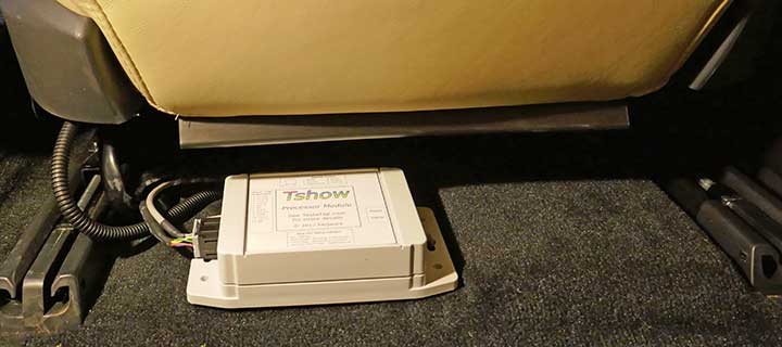
Refreshed processor module under the seat – cables are attached in later steps
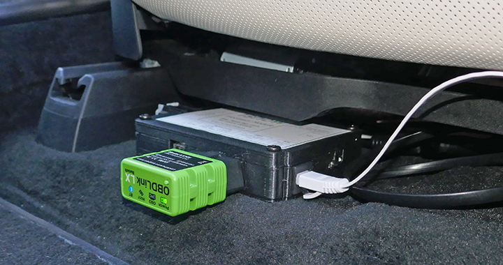
Plaid processor module under seat with OBD-II Bluetooth and OLED white cable attached
There are various cable paths needed for connecting the Tshow processor.
- The Tshow LED assembly at the front of the car
- The diagnostics connector for power and CAN bus connections above the “Cubby”
- The remote control module mounted in the center console.
- The OLED display (mostly for debugging, and is optional)
For Plaid, we used the 20 pin-diagnostics connectors for Vehicle CAN. Pin 9 is CAN+ and Pin 10 is CAN-. Only these two wires are needed. We also got rid of all the intermediary connectors shown in the diagram below (J2, J5, J6) as they are more confusing and unneeded. Vehicle CAN connect to CAN2+ and CAN2-. For power, we connected to the inductive phone chargers, as they have quite a bit of power and are easily accessible. See our Power Tap for access and as one way to make a connection. While the diagnostic connector does have power, unlike the refresh it is quickly turned off when parked. The inductive phone chargers are left on for a longer period but will turn off when parked and sentry mode is off.
Because Vehicle CAN in Plaid/LR/3/Y is 4 times faster (500 kbps) than the earlier S/X CAN 2 (125 kbps), more care is required with the cabling. I originally used a single cable from the Diagnostics connector for power and two CAN buses. This worked fine for years when run at 125 kbps in an older Model S, but seemed to cause problems in the Model S LR/Plaid at higher speeds. The Vehicle CAN at higher speeds is more sensitive to attachments.
I changed the design to separate power into its own single cable, and Vehicle CAN in a separate shielded twisted pair cable. The shield is grounded at the diagnostics connector, and not connected at the other end. While not 100% confirmed, I suspect having two CANs and power (with possible spikes from powering the LED animations) all in the same cable may have induced reflections or crosstalk into Vehicle CAN, causing intermittent CAN failures. CAN is fairly fault-tolerant, but these intermittent problems caused the vehicle to occasionally shut down in a fairly safe manner (with warnings over a minute or so). While a bit nerve-racking, it only required waiting about 20 minutes to recover, at which time everything returned to normal.
Tesla has a diagnostics connector for our 12v power and two CAN busses (a total of 6 wires). You access this connector by pushing straight down on the center cubby (under the 17” display). It is only held in with two clips. You can reach in and pull out two connectors – the 20-pin diagnostics connector is blue (Refreshed/Plaid S, Model X) or black (classic Model S). You’ll also see a white 4-pin Ethernet connector you can ignore. We used the wiring diagram below, but in hindsight the extra connectors (J6, J5, J3) are unnecessary.
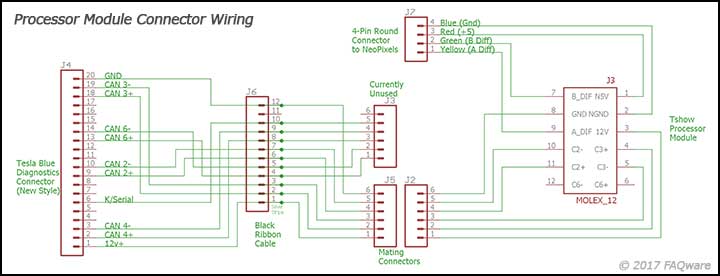
Cables schematic
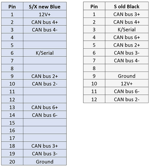
Diagnostics Connector Pinouts
I built a cable that connects the 20-pin diagnostic connector via 8″ of the black 12-wire ribbon cable to one 6-pin female connector. The 6-pin male connector goes to the Tshow processor module female 12-pin connector. While unnecessary, I attached a 2nd 6-pin female connector to the remaining diagnostic leads, perhaps for a future project for other CAN bus connections.
A cable will run from the Tshow 12-pin female connector under the seat to the 6-pin connector in the cubby. This cable uses 22-gauge wires, as it may take up to an amp of power. Using thinner wires is not recommended, but thicker wires are difficult to fit into the 12-pin Molex automotive connector.
Tip – For the cable from the Molex connector, I attached the crimp pins to the cable for the 6-pin male connector, but didn’t insert them in the housing yet. I taped the wires/pins together so it is easier to route. Once routed, the tape is removed and the housing attached.
On the same 12-pin Molex connector, I connected the 6” 4-wire female cable stub. This connects to the cable routed to the front of the car NeoPixels. It is almost impossible to stick an 18-gauge wire into the Molex connector, so we need to add pigtails to the 4 wires. On the open end of the 4-conductor cable, solder 22-gauge pigtail wires and cover with the heat shrink tubing, and shrink. Crimp a terminal to each of the pigtails and optionally solder. See the testing section for how to insert these pins.
Route the wire from under the seat, under the passenger seat track near the center of the car. On the passenger footwell, pull back the carpet and side of the center console a few inches (do not remove it, but you need enough space to run the cables). It is only held in place by snaps, but some force is required to release the snaps. Run the 6-wire cable along the inside of the console cover and up above the cubby. At this point, I attached the 6-pin female housing that will mate with the 6-pin male housing that goes to the diagnostics connector. While slightly different than shown, Plaid is done in a similar way. Remove the inductive phone charger by lifting the unit up and out. This gives you more access to run wires (and to connect to the diagnostics connector).
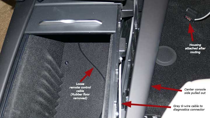
Refresh center console wire routing
For Plaid, I made a 3D printed box holder L bracket and attached the magnets. I mounted the bracket to the side of the larger center storage area with two screws. I mounted it so the cupholders and sliding drawer do not hit the remote.
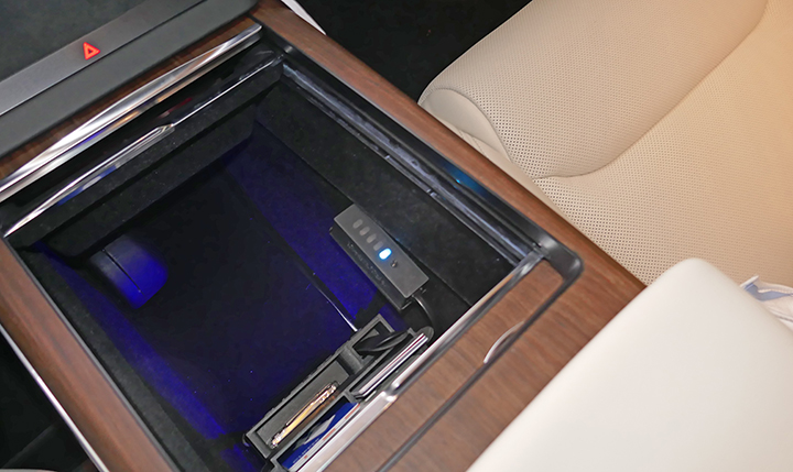
Remote installed in center console
The remote really can be mounted anywhere you can see it and can press the state button. For the Refresh, I elected to place the remote in the center console close to the USB ports, on the passenger side and used tiny magnets to hold it in place. The rubber mat is easy to pull out. I drilled a small ¼” hole in the edge of the plastic where I’ll feed the wire. In the larger console area, the bottom has a rubber mat, which also lifts out.
I used a 6-conductor black modular phone cable. I have a crimping tool and RJ12 6-pin connectors. This makes it far easier to route the wires without the connectors. I attached one RJ12 connector to the Tshow module end of the cable. I routed it along a similar path as the 6-wire that goes to the diagnostic connector, under the seat track and along the inside of the console side cover. There is a hole at the top back of the console where the wire is routed. It’s a bit tricky to feed the wire through this area, so you may need to use a thin solid copper wire to help guide it. With the wire now inside the console, run it along the bottom, passenger side where the rubber floor will cover it. Feed the wire up through the ¼” hole I made earlier. Strip the wires and crimp the 2nd RJ12 connector. You’ll need an extra 8” of cable or so to do this, and once done the excess can be pushed back into the console well. Be sure the wires on this cable have the same color wire on pin one of both connectors. Also, be sure the flat orientation is correct so it fits into the remote module without a twist.
Bizarre side story – The loose phone cable I purchased was defective and had 6 wires on one end, and only 5 on the other. I didn’t notice it while crimping the connectors and I spent at least an hour trying to figure out why it wasn’t working. I had to remove that cable and start over with a replacement cable. Never encountered anything like it before!
I cut a small slice in the large console rubber mat where the wire goes, but it likely is unnecessary. Insert the large rubber mat into the console floor. Ideally, the wire will fit into the channel and not make any bumps in the console floor.
On the smaller rubber mat, I cut a small cutout where the cable will feed to the remote module. Confirm the fit is correct. Remove the mat. Using the remote cover that has the 3 tiny magnets, I temporally attached 3 more magnets to the underside of the cover. Next, I placed the cover on the rubber mat in the location where it needs to reside. I added three more magnets to the underside of the rubber mat. You may want to test the location by inserting the mat and confirming the location with enough room for the remote box when attached to the cover and that the console cover can close.
With the position set, carefully remove the mat. I then added a small dab of epoxy to each of the 3 magnets on the underside of the mat (not to attach to the mat, but to attach to the plastic under the mat. Carefully insert the mat and press down on the cover to get a good bond between the magnets and the plastic of the console.
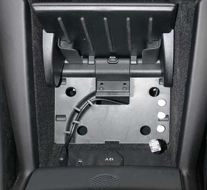
Three magnets and RJ12 connector attached to the wire
After the epoxy is set (24 hours), remove the 3 temporary magnets and attach the lid to the remote module. Attach the RJ12 connector and set it in place. Push any excess cord down under the console.
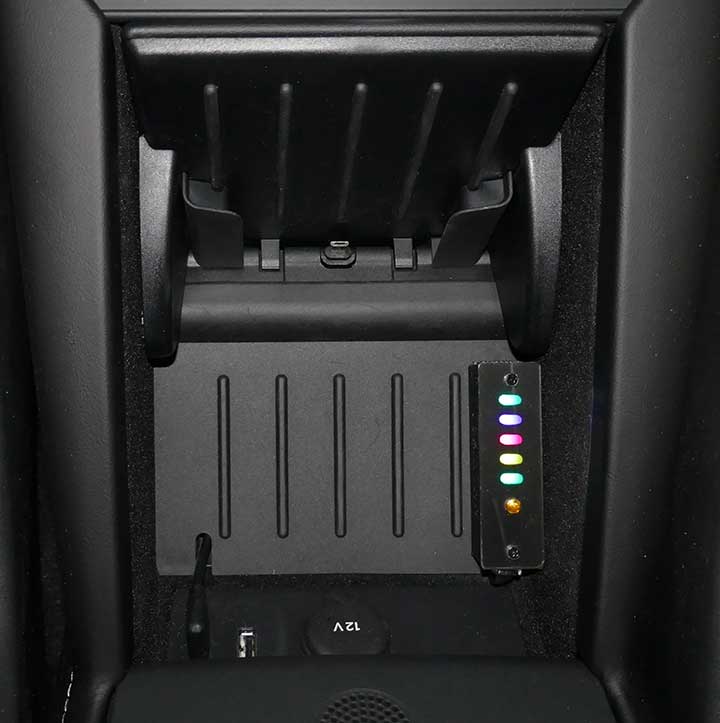
Finished V1 remote installation
Tesla now makes the service manual available for free. Create an account and select an individual subscription. The cost is $0. Once logged in, follow the Fascia Assembly – Front for removal instructions. For the first time, expect it will take an hour to remove. It can be done without a lift, but you do have to reach under the car to remove some bolts. The instructions in steps 13 and 14 suggest separating 4 connectors. I had success with the 16v Lithium-Ion connector, but I was unable to separate the responder’s loop connector and bumper connectors even with the latches unlocked. I found it wasn’t necessary and you only need to pull the bumper out 8″ or so. I placed two cardboard boxes under the bumper to support it once I pulled it out. There is a hidden plastic alignment pin in the center bottom cover near the firewall. Pull down a bit on the cover before pulling the bumper forward. Similarly, when trying to reassemble later, that plastic pin must go in the hole to make all the other screw holes line up. It’s likely easy if you have a lift. A lot harder when you can’t see it well and you’re on your back!
I expect the way Tesla intended the T-badge assembly replacement is by removing the entire front bumper fascia. Not knowing how to do that at the time, I did it without touching the bumper, but it s almost impossible. A second time I ended up removing the bumper, and while not simple, it was easier. Tesla now makes the service manual available for free. Create an account and select an individual subscription. The cost is $0. Once logged in, follow the Fascia Assembly – Front for removal instructions.
My first car was a refreshed RWD S, with the Biohazard filter. Other configurations may differ slightly, so you may need to improvise as needed. The video is for the 2016 S.
With the frunk open, remove the center rear cover, the two side covers, and then the small front cover. These all snap out, there are no screws or bolts. Remove the cabin air intake by first removing the two rubber drain tubes on the sides, releasing the two pull snaps above the drain hoses, and releasing the 3 plastic locking snaps near the windshield. The unit should lift out of place. Below that is the air duct to the cabin. It simply lifts up a few inches and then pulls out towards the front of the car.
Pull off the large rubber seal that is around the tub. Remove the inner liner tub being careful to disconnect the LED and release button wires. The LED module connector is latched and is slightly tricky to release.
There are two 10m bolts that hold the tub in at the bottom left and right ledges. All the other bolts can be left in, as they hold the cabin filter. (The video shows two additional bolts being removed from the side of the ledges, but they can be left in). Release the two plastic locking snaps in the front and remove the tub, while pushing the wires and rubber gasket out.
The firewall is exceptionally difficult to get to from the cabin and the frunk area. You would likely need to disassemble many parts to attempt to route wires through the firewall. After much consideration, we gave up on trying to route through the firewall and elected to go through the passenger door seal. Turns out it is quite easy to route the wire from the frunk along the side and into the door hinge cavity.
Running the cable along the side
Remove the passenger sill (snaps up and back). From the door hinge area, I poked a hole at the top of the rubber gasket. Do not cut with a knife or it will split and allow water into the cabin. I soldered a 12″ length of 12 AWG wire (from leftover Romex) to the four wires and covered it with several layers of shrink wrap. Poke the 12 AWG wire through the hole and grab it from the cabin side. Pull hard to feed the wire through the hole. It should be quite tight, providing a watertight seal.
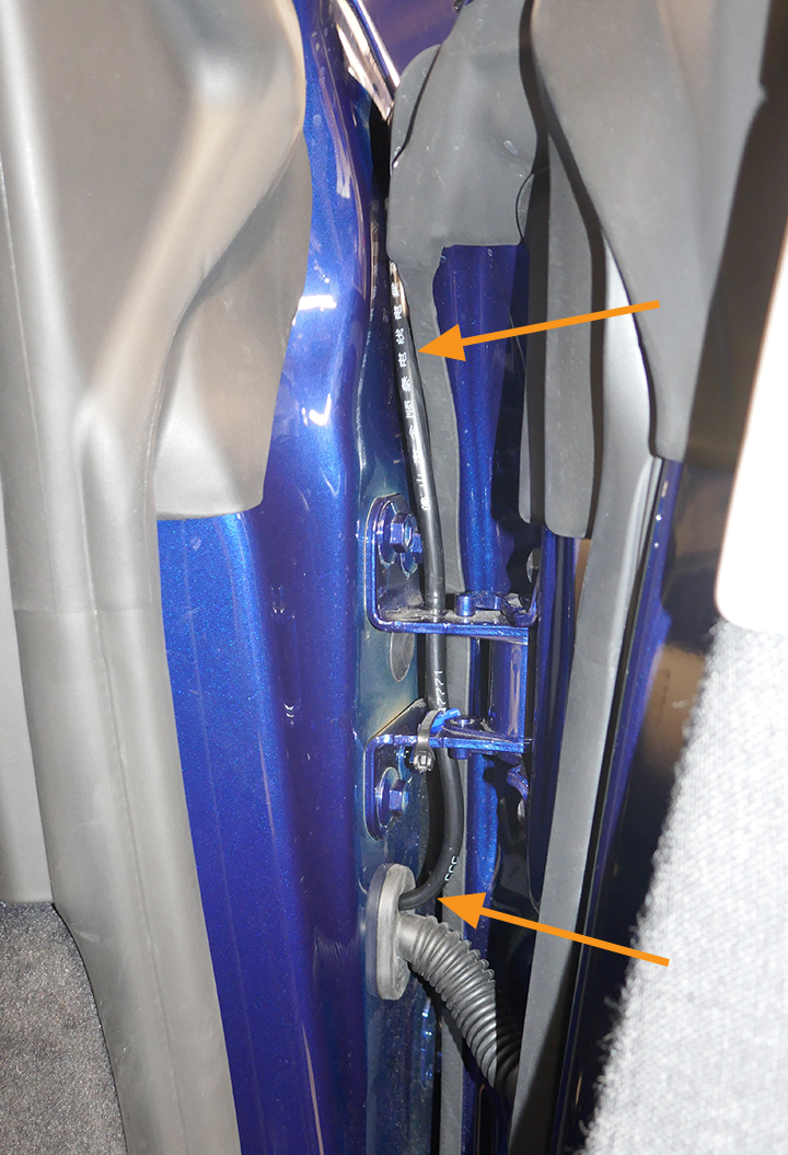
Wire fed through door grommet
There is another smaller rubber grommet between the hinge. As far as I can tell it is blocked by a layer of aluminum behind the grommet, so not useful. I added a tie wrap on the hinge to keep the wire in place. Check carefully that the wire does not impede the hinge or the rubber seals. In the cabin, I routed the wire along the bottom of the sill and under the seat rail to the processor.
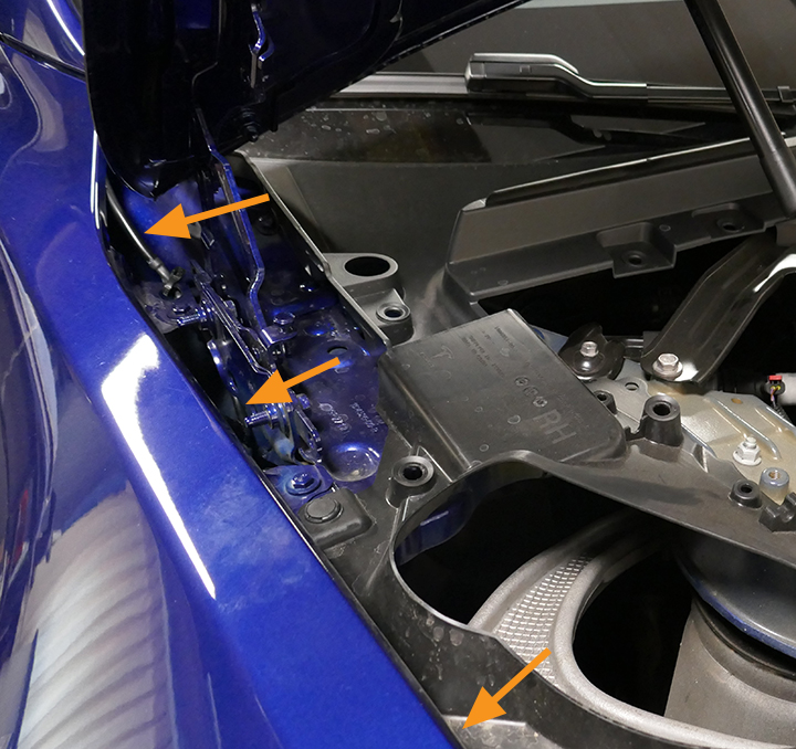
You may elect to use the Plaid option above, but we show how we did it on my refreshed Model S (RWD), as there was a hole I could access in the firewall, sealed with a black grommet. It is located about 10” down from the windshield and a few inches from the side of the car. It was partly covered by an aluminum foil sheet that I folded back. I think it was intended for a drain line for cars equipped with the pano roof.
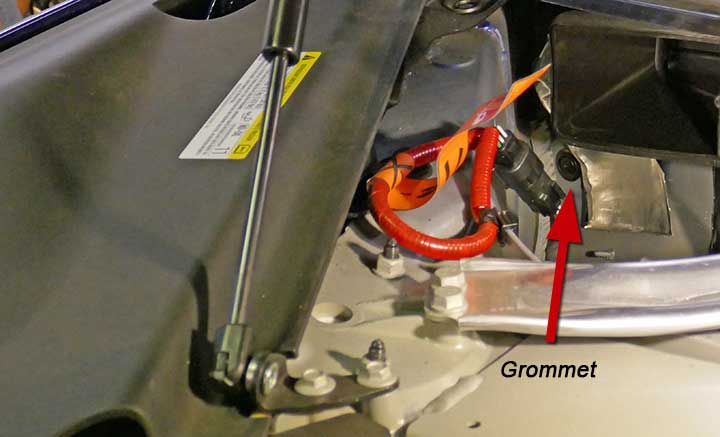
Grommet in firewall
Remove the grommet. Remove the front passenger door sill plate. The cable with the connector attached will fit through the hole and through a second hole about an inch in that comes out just above the passenger cabin fuse box.
You may need to thread a thin wire or string first and then pull the cable and connector through the firewall. I cut a hole in the grommet slightly larger than the cable, and a slice to the edge of the grommet so it can be placed over the cable and reinserted into the firewall.
I routed the cable around the fuse box and down into the sill area with the other large cable bundle resides. When near the B-pillar I routed the wire under the seat track and under the carpet and out through the existing cut carpet patch. You only need an inch or two of cable exposed under the seat. I used a couple of tie wraps to keep it all neat in the cabin.
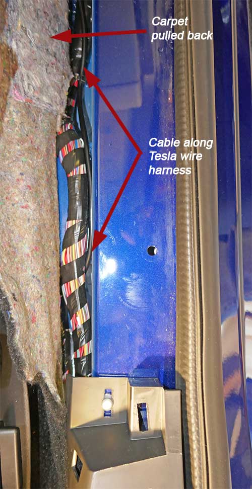
Routing wire along sill
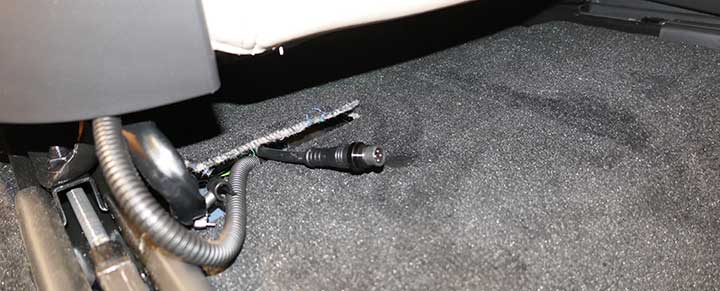
End of our cable under the seat through existing carpet cutout
Back in the frunk area, I applied some silicone around the grommet to seal out water and noise. Route the rest of the wire around to the front. I use a couple of tie wraps and adhesive pads to keep it all neat. Tip: first clean the area with alcohol when you plan to attach an adhesive pad. We’ll install the Tshow assembly next and attach its connector.
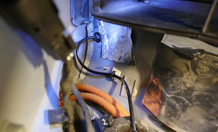
Wire through the grommet and sealed
Ideally, you’ll have the bumper partly removed. Unscrew the three T25 screws that hold the T-Badge assembly to the bumper.
There are four snaps holding it to the plastic part of the bumper. Push the assembly towards the windshield to release these snaps. You may need a plastic pry tool to help (don’t use a metal tool). Once released, it should come right out. For Plaid, there is a Bluetooth module attached. Remove the two screws holding it on and set it aside. You don’t need to disconnect it.
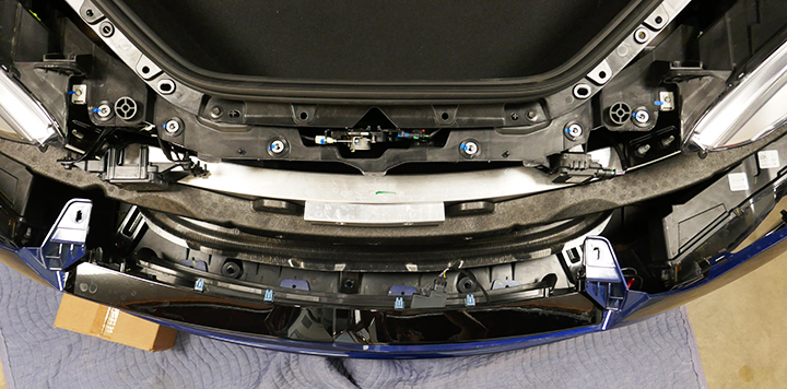
Plaid bumper disconnected and T-Badge removed
Prepare to install the new assembly with the LEDs. For Plaid only, attach the Bluetooth module with two screws.
Move the T-Badge assembly into place and push onto the four snaps of the bumper. Luckily the extra thickness of the 0.062 thick polycarbonate doesn’t cause a problem. Install the three T25 screws.
Connect the 4-pin connector to the cable and confirm that it works!
Complete the rest of the bumper reassembly.