This non-destructive tap provides switched power from the inductive phone chargers in a Model S/X 2021+ LR/Plaid and possibly the Model 3/Y. We have confirmed you can pull at least 2 amps via this connection when no phones are charging. See our Accessory Power Guide for access to the inductive phone charger power and other connection options. (Aug-2025 update)
There are a number of ways this could be constructed. We chose to solder the terminals directly to the male connector, which is described below. The Green Lock is not needed for the direct connection.
One could use short wires between the female terminals and the male connector as another approach, which eliminates the need for the 3D printed cover. The Green Lock is inserted after the terminals with wires are inserted.
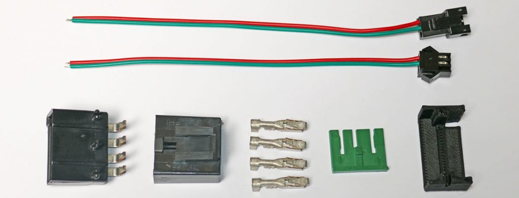
1 – Delphi Green Lock 15324456 ($0.29, not needed)
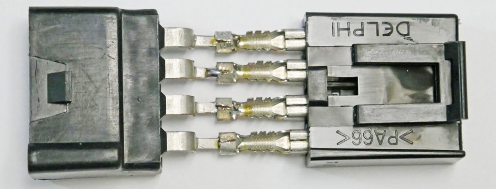
1 – Delphi 4-pin Male Connector 12110440 ($11.01)
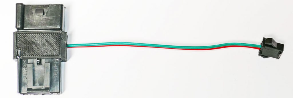
1 – Pair of wired mini-connectors ($1.43, optional)
1 – 3D Printed cover ($8-15 from 3DHubs.com, optional, see below )
Epoxy, Silcone and solder as needed
The prices above are from Mouser and other suppliers as of June 2023 and do not include the supplier’s shipping fees.
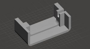
3D Printed Cover
We made a 3D printed cover to insulate the exposed electrical connections and mount the two housings close together. We used Black PTEG filament. ABS filament should work fine too. PLA should not be used as it will deform under high cabin heat. For layer height we used 0.2 mm.
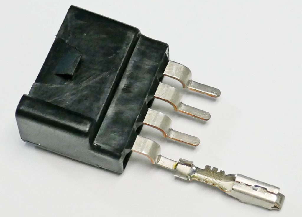
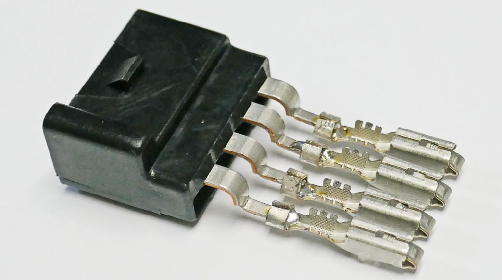
On the male connector, cut off the 3 small plastic protrusions that are used for PCB mounting. Bend the thin portion of the rear tabs at a 90-degree angle, making them all in line. Solder one terminal in the orientation shown, spaced from the bend by about 3-5 mm. Bend the terminal tabs over the solder joint with needle-nose pliers (or the tabs can be pre-bent before soldering).
Repeat with the next 3 terminals. It’s important to keep all four terminals closely aligned in a row as shown so they will fit into the housing.
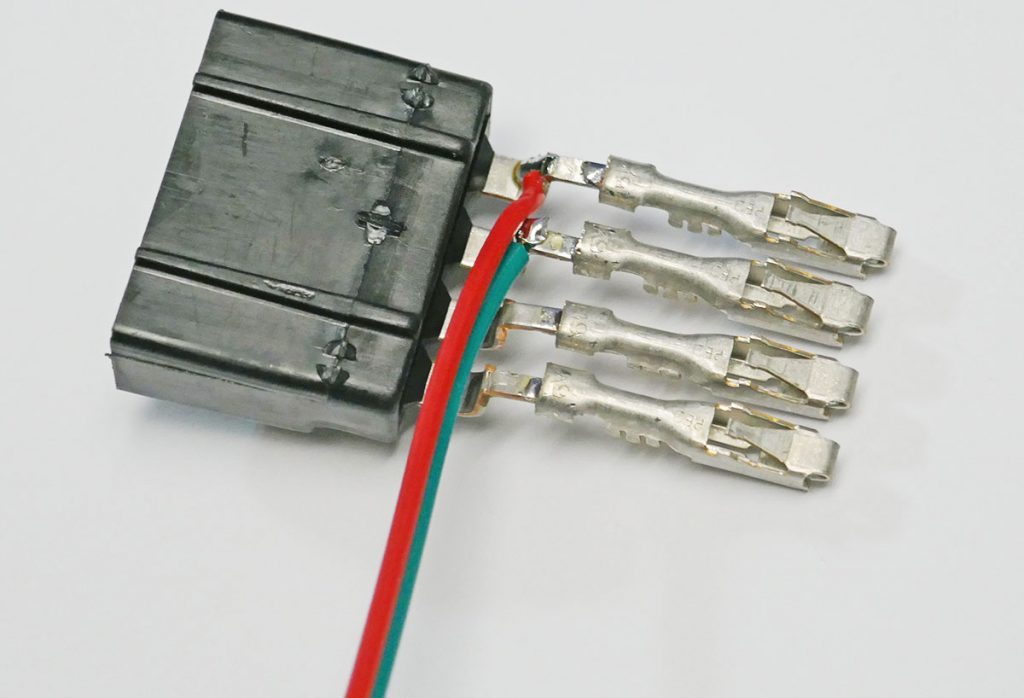
Flip over the assembly and check that it fits into the female housing, but don’t push it in just yet. The terminals only go into the housing one way.
Flip the assembly and attach the power wires from the small 2-pin male connector. The red lead (+12v) is soldered to the “D” position and the green ground is soldered to the “C” position. The positions A B C D have raised letters on the top side of the female housing. The wire feeds out towards the “A” terminal.
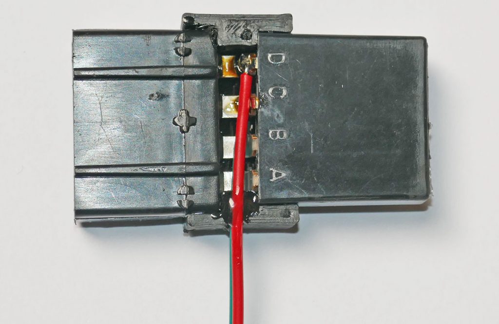
Push the terminals fully into the housing until they lock. Test fit the 3D printed cover. Remove the printed cover and apply a thin layer of epoxy on the surfaces to be mated with the housings and slip the cover into place. After the epoxy cures, the exposed side could be filled with thick silicone. Since the top side is not exposed once connected, it’s not important that it be sealed, but we used silicone (not shown).
Here is the opposite side of the completed assembly.
Installation
The power tap is inserted between the power connection and the inductive phone charger as shown in our short video.
Wire Routing
The Power Tap is used for a variety of projects. Here are the basics of running the wire from a dashcam or radar detector near the rearview mirror on a 2021+ Model S LR/Plaid. Routing over and down either side will work.
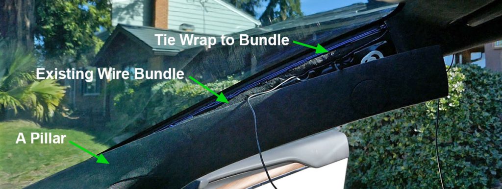
Push the wire into the headliner. On the A-pillar, it snaps out from the top. You don’t need to pull it out but route the wire along with the existing wire harness, so it doesn’t interfere with the side airbag. I used a couple of tie wraps to hold the wire in place.
Remove the short side panel that has the door gasket slightly overlapping. Pull out from the top and slide up to release. Remove the dash side panel. It snaps out with a pry tool. The first 22 seconds of our Electroluminescent lighting project video demonstrates the process.
Feed the wire down from the A-pillar into the dash and below. This can be done without pulling out the A-pillar cover.
Remove the under-dash trim. It’s only held in with magnets, so just pull downwards and it should release. If you are working on the passenger side, you’ll need to disconnect the small speaker that is attached to the under-dash trim.
Now you can route the wire behind the side carpet, behind the footwell carpet, over to the center console.
Lift up the inductive phone chargers and pull forward to fully release as shown in our Power-Tap video. You’ll see slots on each side of the center console.
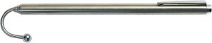
Use a wire reacher or an unbent coat hanger with a hook that is at least 18″ long.
There are slots on each side of the console where you can slip the wire reacher and hook the wire and pull it up into the area under the wireless phone chargers.
Follow the video to install the Power-Tap and connect the power.