There are a number of locations where you can tap power to add accessories such as dashcams, radar detectors, tire inflators, and more. We examine some of the more popular locations and explain the various limitations and appropriate uses. (Jun-2023)
Here is a sample list of common powered accessories and the power they require. Most devices rated for 12v will work from 10 to 16 volts. Some devices may work best with power 24/7, such as a dashcam, while you may prefer that others turn off when the car is off.
USB to Dual SD Card Reader, with two 128 GB cards, 100 mA (5v), 0.5 W
HVDI Wireless Phone Charger, 1250 mA, 15 W
SiriusXM SXPL1V1 Onyx Plus Satellite Radio, 500 mA, 6 W
SSD Drives
Crucial X6 2 TB, 800 mA (5v), 4 W Peak
Samsung T5 1 TB, 700 mA (5v), 3.5 W Peak
SanDisk Extreme PRO V2 1TB, 1000 mA (5v), 5 W Peak
12 volts or 16 volts?
For decades vehicles use a “12-volt” system for accessories, controls, lights, and more. ICE vehicles with lead-acid batteries and an alternator for charging usually mean a typical voltage of 13 to 14 volts. For older Tesla vehicles that use an AGM lead-acid battery in combination with an inverter charger, the voltage normally runs a little higher, in the 14-15 volt range. Today’s Tesla vehicles use a Lithium-Ion 16v battery for accessories, controls, lights, and computers. This typically has a system voltage in the 15-16 volt range. All these systems are commonly referred to as 12v systems, even though the voltage is often quite a bit higher.
We generally use “12v” to include all systems which provide 12 to 16 volts. In videos, we show the actual voltages we encountered on Tesla vehicles.
Power States
Our analysis shows the results of each connection’s voltage state in various vehicle modes. Other than the vehicle’s “On” state, the car is locked with no people inside. We did note that the car locked or not locked does not change the results. We also tested HVAC modes with Sentry off, such as Keep, Dog, and Camp modes.
Out test results apply to S/X/3/Y with MCU 2 or Z processors. MCU-Z first appeared in S/X Plaid/LR, in June 2021. MCU-Z began to ship in the 3/Y in Q1-2022. We have not gotten an older S/X with MCU-1 to test yet.
We tested each connection as noted with a resistive load and confirmed no error messages appeared. Using a higher load may risk blowing a fuse or tripping the electronic fuse. Tesla does specify the Power Socket can handle a peak current of 16 amps, with a continuous current of 12 amps.
Items shown with a delay indicate the power remains until the delay period expires. These may remain on for a longer period of time if data is being downloaded or uploaded, the car is being connected via the phone app, charging, or the glycol pumps are running to heat or cool the battery.
S/X with MCU-Z, Lithium-Ion 16v, and Electronic Fuses
Type
Location
Current
Notes
On
Off Sentry On
Off, Keep, Sentry Off
Off, Dog, Sentry Off
Off, Camp, Sentry Off
All Off Sentry Off
Diagnostics
Below center screen
1 A*
12v
12v
12v
12v
12v
0v, delay 3
Drive control
Under front phone chargers
1 A*
12v
12v
12v
12v
12v
12v
OBD-II
Under driver footwell
1 A*
12v
0v
0v
0v
12v
0v
Phone Charger
Center Console
2 A*
12v
12v
12v
12v
12v
0v, delay 1
Power Socket
Center console
12 A**
12v
0v
0v
0v
12v
0v
Power Socket
Trunk left side
12 A**
X only
12v
0v
0v
0v
12v
0v
USB
Front center console
1.9 A*
5v
5v
5v
5v
5v
0v, delay 1
USB
Rear center console
1.9 A*
5v
5v
5v
5v
5v
0v, delay 1
USB
Glovebox
1.8 A*
5v
5v
5v
5v
5v
0v, delay 2
* Tested >30 seconds at specified current
** Recommended maximum amperage, limit not tested
Delay 1 occurs 8.8 minutes after door close
Delay 2 occurs 9.2 minutes after door close
Delay 3 occurs 9.6 minutes after door close
S/X with MCU-2, AGM 12v, and Physical Fuses
Type
Location
Current
Notes
On
Off Sentry On
Off, Keep, Sentry Off
Off, Dog, Sentry Off
Off, Camp, Sentry Off
All Off Sentry Off
Diagnostics
Below center screen
1 A**
12v
12v
12v
12v
12v
12v
Intrusion
Behind microphone panel
1 A*
S only
12v
12v
12v
12v
12v
12v
Mirror
Connection at mirror
1 A*
12v
12v
12v
0v, delay 1
12v
0v, delay 2
OBD-II
Under driver footwell
1 A*
12v
12v
12v
12v
12v
12v
Power Socket
Center Console
12 A**
12v
0v
0v
0v
0v
0v
Power Socket
Trunk left side
12 A**
X only
12v
0v
0v
0v
0v
0v
Sill
Under driver's sill***
1 A**
S only
12v
0v
0v
0v
0v
0v
USB
Front center console
1.9 A*
12v
5v
5v
0v, delay 1
5v
0v, delay 1
USB
Rear center console
1.9 A*
5v
0v
0v
0v
5v
0v
USB
3rd Row
1.9 A**
X only
5v
0v
0v
0v
5v
0v
* Tested >30 seconds at specified current
** Recommended maximum amperage, limit not tested
*** Only powered when driver door open
Delay 1 occurs 1.5 minutes after door close
Delay 2 occurs 2.1 minutes after door close
3/Y with MCU-2, AGM 12v, and Electronic Fuses
Type
Location
Current
Notes
On
Off Sentry On
Off, Keep, Sentry Off
Off, Dog, Sentry Off
Off, Camp, Sentry Off
All Off Sentry Off
Diagnostics
Rear center console
1 A**
12v
untested
untested
untested
untested
untested
Phone Charger
Center Console
1 A**
12v
untested
untested
untested
untested
untested
Power Socket
Center console
12 A**
12v
12v
12v
12v
12v
0v, delay 1
Power Socket
Trunk left side
12 A**
Y only
12v
12v
12v
12v
12v
0v, delay 1
USB
Front center console
1.9 A*
5v
5v
5v
5v
5v
0v, delay 1
USB
Rear center console
1.9 A*
5v
5v
5v
5v
5v
0v, delay 1
USB***
Glovebox
1.9 A**
5v
5v
5v
5v
5v
0v, delay 1
* Tested >30 seconds at specified current
** Recommended maximum amperage, limit not tested
*** added to vehicles built ~2021
Delay 1: more than 5 minutes after door close
3/Y with MCU-Z, Lithium-Ion 16v, and Electronic Fuses
Type
Location
Current
Notes
On
Off Sentry On
Off, Keep, Sentry Off
Off, Dog, Sentry Off
Off, Camp, Sentry Off
All Off Sentry Off
Power Socket
Center Console
12 A**
12v
12v
12v
12v
12v
0v, delay 1
Power Socket
Trunnk
12 A**
12v
12v
12v
12v
12v
0v, delay 1
USB
Front Center Console
1.9 A*
12v
12v
12v
12v
12v
0v, delay 2
USB
Rear Center Console
1.9 A*
12v
12v
12v
12v
12v
0v, delay 2
USB
Glovebox
1.9 A*
12v
12v
12v
12v
12v
0v, delay 2
* Tested >30 seconds at specified current
** Recommended maximum amperage, limit not tested
Delay 1 occurs 2.4 minutes after door close
Delay 2 occurs 2.7 minutes after door close
Access Locations
There are many locations where you can get power for accessories. We’ve identified frequent locations owners like to use, either for the physical location or how it provides power.
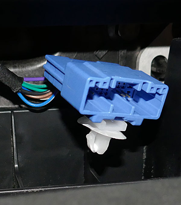
Diagnostics Connector
The Diagnostics connector provides limited power and operates differently depending on the vehicle type and vintage.
Model S/X 2021+ LR/Plaid: the blue connector is accessed after removing the phone chargers, then pulling down the diagnostics panel. Video 1 shows in detail. Pin 1 = 12v, Pin 20 = Ground. Model S/X Made from Sep-2015 to Dec-2020: Pull down the cubby below the display to access the blue connector. Video 2 shows in detail. Pin 1 = 12v, Pin 20 = Ground. Model S/X Made before Sep-2015: Pull down the cubby to access the black connector. Pin 10 = 12v, Pin 9 = Ground.
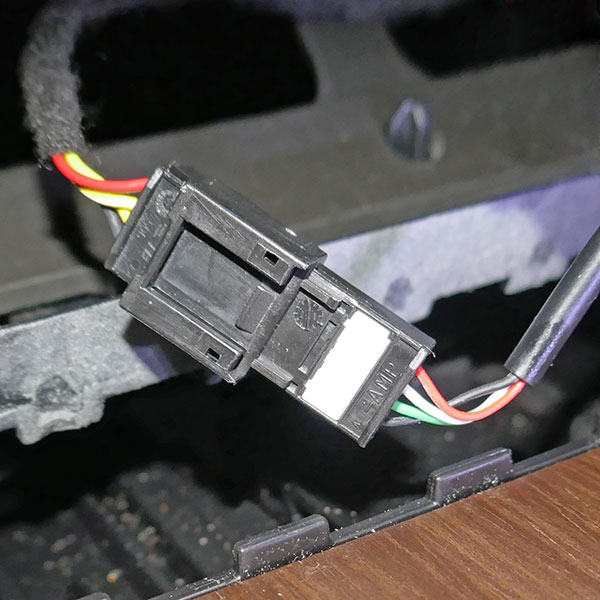
Drive Control Connector
The drive controls consist of the touch buttons adjacent to the emergency flashers to set the drive modes Park, Neutral, Drive, and Reverse. This can source 1 amp, but at 2 amps it will “blow”. It’s a good source for a dashcam, as most dashcams require less than 500 mA.
Model S/X 2021+ LR/Plaid: the black 4-pin connector is accessed after removing the phone chargers. Video 1 shows in detail. The outside pins provide power. The red wire is 12v, and the black wire is Ground.
Intrusion Alarm Connector
Enhanced Anti-theft optional alarm module helps to identify glass breakage and set off the alarm in the Model S.
Model S manufactured from 2012 to 2020: the black 4-pin connector is accessed after removing the microphone panel. Video 2 shows in detail. In a few vehicles (2014-2015?) the connector is taped up inside the headliner wire bundle and may be harder to locate. The connector is available even if the intrusion module is not installed. Pin 1 = 12v, Pin 3 (black wire) = Ground. Our dashcam cable article explains more so you can make your own connections.
Mirror Connector
The rearview mirror has power and data to control the automatic dimming. Mirror power is not available on the 3/Y and new 2021+ LR/Plaid.
Model S/X manufactured from 2012 to 2020: the black 5-pin connector is accessed behind the mirror panel. Video 2 shows in detail. Pin 1 = 12v, Pin 5 (black wire) = Ground.
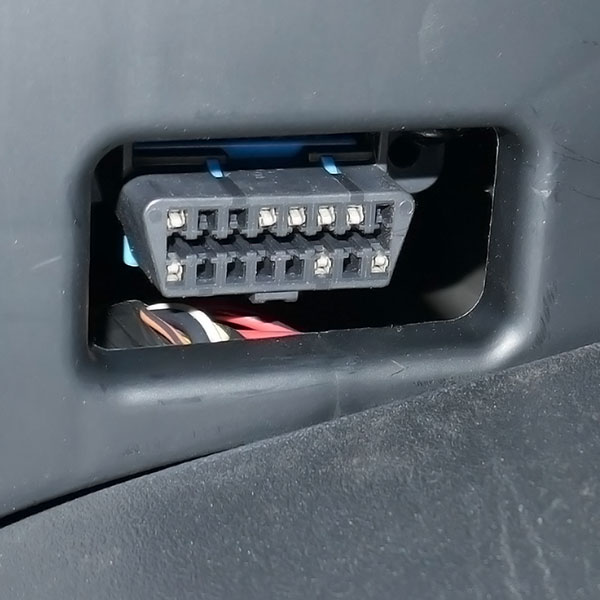
OBD-II Connector
OBD-II (On-Board-Diagnostics) connector is required for environmental checks in ICE cars. The Model 3 and Model Y do not have an OBD-II connection.
Model S/X: The OBD connecter is available under the dashboard on the driver’s footwell. Videos 1 and 2 show in detail. Pin 16 = 12v, Pins 4 & 5 = Ground.
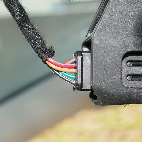
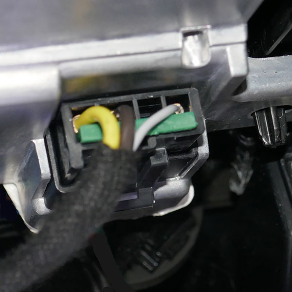
Phone Charger Connector
The inductive phone charger is a higher power connection, that can charge two phones, each at 15W or so. We’ve tested this to 2 amps with no phones charging. See our Power Tap project which includes a video to access this connector.
Model S/X 2021+ LR/Plaid: The yellow wire Pin D = 12v, the brown wire Pin C = Ground. Model Y: Connections are available, but we don’t have the pinout yet. Model 3 Made around June-2020 and later:Connections are available, but we don’t have the pinout yet.
Power Socket
Commonly called the cigarette lighter socket, the power socket is the standard for 12v power in all vehicles.
Model S/X/3/Y: Located in the center console. Model X/Y: An additional Power socket is located on the driver’s side in the rear trunk area.
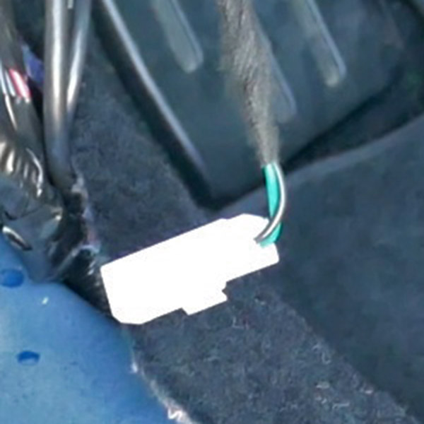
Sill Connector
Model S Made from Sep-2015 to Dec-2020: This 4-slot white connector offers 12v power only while the related front door is open. It is not connected to anything. You must remove the sill to gain access. See video 2 for details. Only two wires are loaded into the connector. The green wire = 12v, the black wire = Ground.
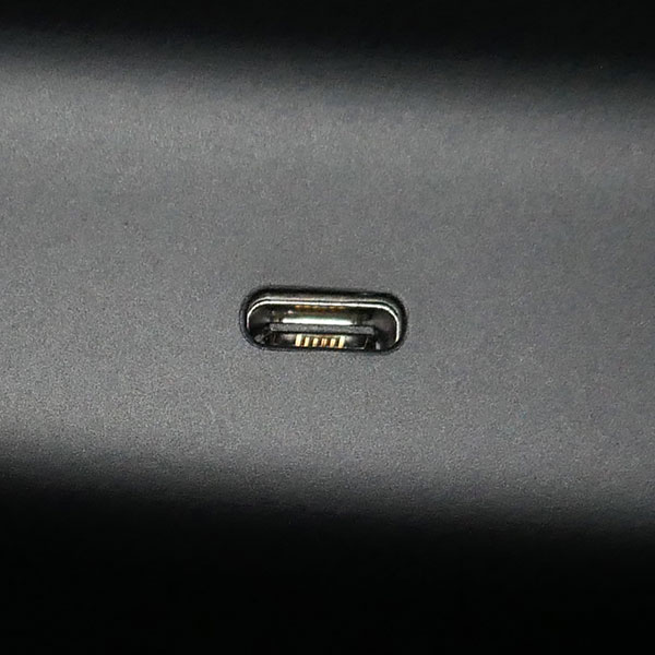
USB Ports
Each USB port offers a 5v connection. Older vehicles use only 2 USB-A ports. Newer ones use a mix of USB-A and USB-C ports. The newest vehicles include a USB-A port in the lockable glovebox, along with 2 in the front center console, and 2 at the rear center console. The Model X includes another USB charging port for the 3rd row.
Model S/X with MCU-1: Our testing shows the current is limited to about 600 mA (slow charging). All other variants: Supports fast charging, likely to 2.4 A. We tested to 1.8-1.9 A.
Untested Power Sources
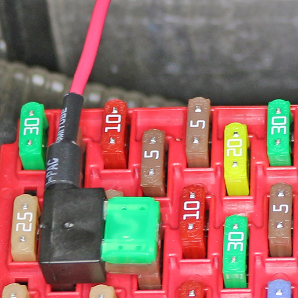
Add-a-Fuse
Some owners tap into a fusebox on an older S/X, manufactured prior to 2021. Add-a-Fuse products allow a wiretap into a fuse box. Check out our Fuses and Current Protection article for the location of fuse boxes and the functions. An empty fuse slot may work as well, but you’ll have to check if it is a switched or unswitched slot. To maintain proper circuit protection, never replace the fuse with a higher amperage fuse. Be careful with the Add-a-fuse orientation. In one direction, your tapped wire is fused, and in the opposite direction, it is not fused at all!
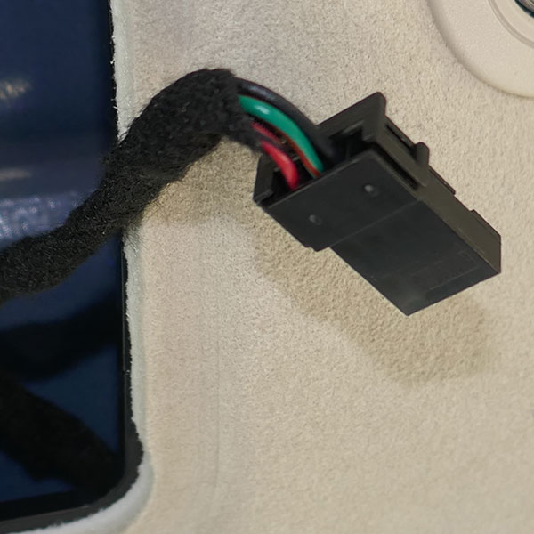
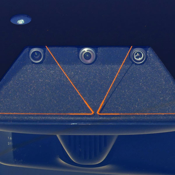
Camera Power
Reportedly, switched power is available inside the center-upper camera housing. We’ve been unsuccessful at opening this up. It requires quite a bit of pressure to remove the mirror and camera housing. It exceeded our personal threshold for possible damage. We know some owners have succeeded and one broke the windshield getting into this area.
Pre HW4 Model S/X with cameras, Model 3/Y: If you get access, the white connector with a black and green wire should offer switched power. The green wire = 12v, the black wire = Ground.
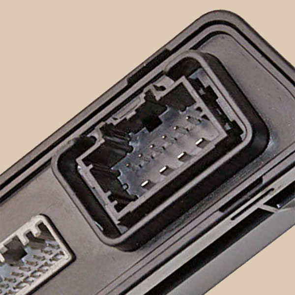
Trunk/Liftgate Power
Model S 2012-2020: The liftgate module is located in the trunk, passenger side, near the Subwoofer. You’ll have to remove the side carpet to get access. At the module, the red.gray wire Pin 8 = 12v, the black wire Pin 7 = Ground.
Model X 2015-2020: The rear body control module is located under the trunk floor carpet behind the rear wall trim. While this module is powered, we have not confirmed if switched or unswitched. At the module the white 16-pin connector, the red wire Pin 16 = 12v, the black wire Pins 11 & 16 = Ground.
Connectors Without Power
There are many connectors without power, but we list several that you may expect to have power, but do not!
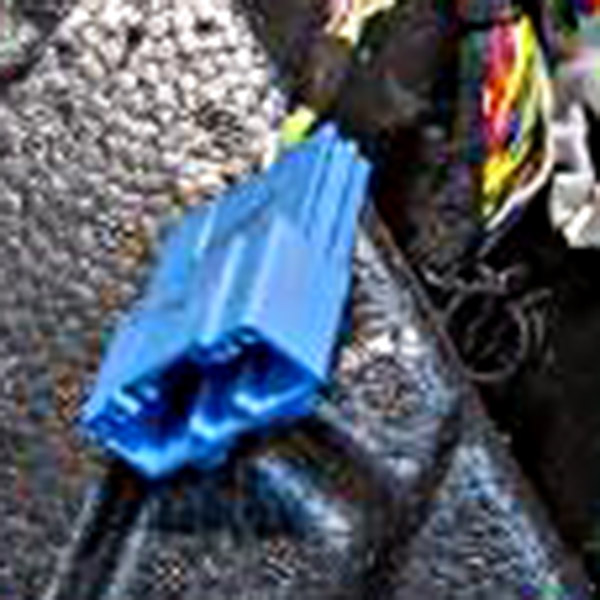
CAN Bus Connector (3/Y)
The Model Y (all) and the Model 3 (after 5-Oct-2020) have a blue CAN bus connector on the right side of the passenger footwell, behind the carpet. While this looks the same as the powered Model S/X diagnostics connector, there is no power available on this connector. (This is reported from other owners, as we have not verified this ourselves).
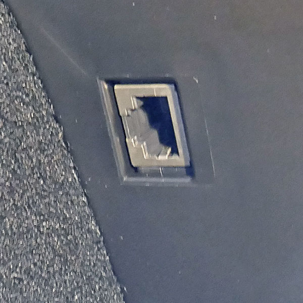
Ethernet Connector (3/Y)
The Model Y and the Model 3 have an 8-pin RJ45 Ethernet connector under the dash in the driver’s footwell. There is no power available on this connector.
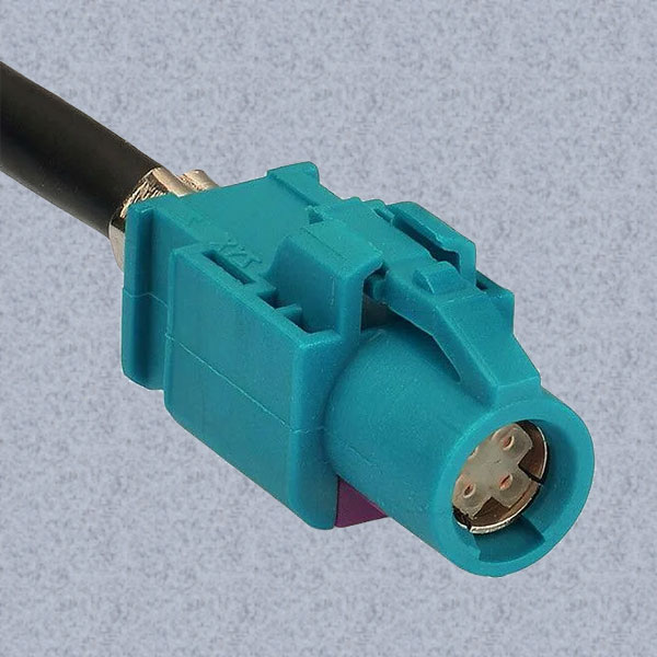
Ethernet Connector (S/X)
The Model S and the Model X have a 4-pin Fakra Ethernet connector above the center console. There is no power available on this connector.
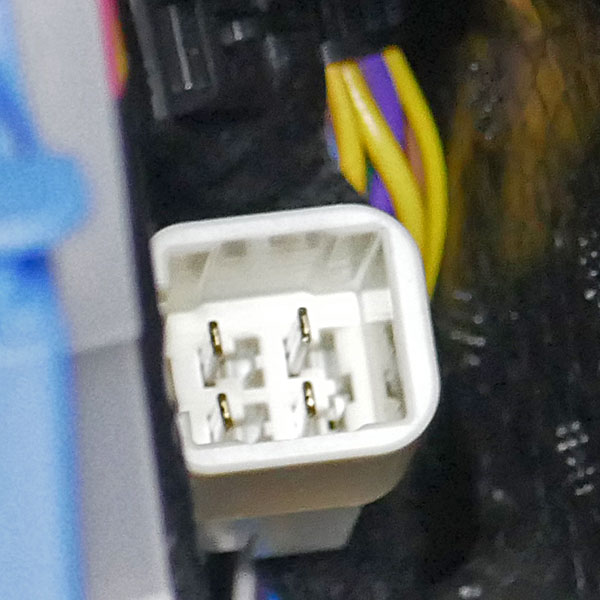
Trailer Brake Controller (X/Y)
The Model Y and the Model X have a 4-pin open connector behind the carpet on the side of the driver’s footwell. Unconfirmed, the Model S and 3 may also have this connector. We were unable to detect any power at this connector, although it is reported that power appears when a trailer is connected and software enables trailer operation. Our tests were on a 2022 Model Y without a trailer hitch. Tesla sells a mating connector with wire pigtails, part number 1072586-00-A.
Videos
We made several videos that show where we connected up, the voltages encountered, and some of the state changes. We did further tests not shown in the videos and recorded all the results in the prior Power States section.
Video 1: 2021 and later Model S/X LR/Plaid
Video 2: Model S/X (Oct-2016 to Dec-2020) with MCU-2
All Model S/X made from Mar-2018 to Dec-2020 include MCU-2, but Model S/X made from Oct-2016 to Feb-2018 include MCU-1 unless the Tesla MCU-2 retrofit was purchased and installed.
Connections
There are a number of ways to wire into your Tesla. Here is our opinion on the best and worst ways to make your connections!
Best
This category covers those locations that require no removal of any panels and is generally recommended by Tesla for accessories. This includes the USB ports, the power sockets, and the ODB-II connector (only on S/X).
Pros
Easy access
Standard connectors
Low risk
Cons
Easy to dislodge
Can be unsightly with visible wiring
Limited locations
Good
Using an available connector or connector bridge offers access to alternative locations and power types, while keeping your wiring hidden. Connecting into the diagnostics connector, inserting between the inductive phone charger with the Power Tap, or inserting between the intrusion module connectors with the Dashcam Power Cable (Model S) are good choices.
Pros
Hidden wiring
Reliable connection
Many location choices
Cons
Special connectors required
Limited access
Not Tesla recommended
Fair
Tap into the back of a connector or use some type of wiretap. Using connector pins, crimped and soldered to wires, these pins are then inserted into the back of a connector. Surprisingly, they work fairly well for low currents on smaller connectors. Use tie wraps on the cable to keep the pins from being pulled out. You can also tap directly into a wire using various wiretaps. These punctures the wire to make the connection. Look for Posi-tap or T-tap connectors.
Pros
Hidden wiring
Low cost
The most location choices
Cons
Less secure and less reliable, may damage wires
Difficult to access
Not Tesla recommended
Poor
Cut the desired wire and solder/tape the joint, or cut and use a wire nut to connect your power. Both of these techniques can work, but are not reversible and are likely to fail over time with the harsh automotive environment.
Pros
Hidden wiring
Low cost
The most location choices
Cons
Not reliable over time, damages wires
Difficult to access
Not Tesla recommended
Behind the Scenes
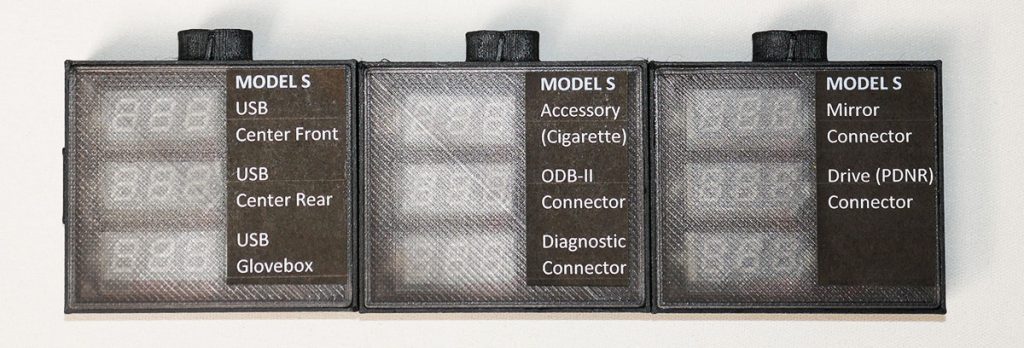
This is one of those projects that seemed trivial to start and got more complex as we went along. We could have just used a simple voltmeter, but with all the tests needed, we knew it would be easier with a group of voltmeters that could be viewed at the same time while recording the state changes when each vehicle is shutdown.
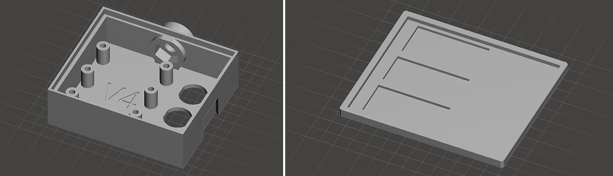
We designed and made a 3D enclosure and translucent lid to hold 3 voltmeters and associated rear connectors.
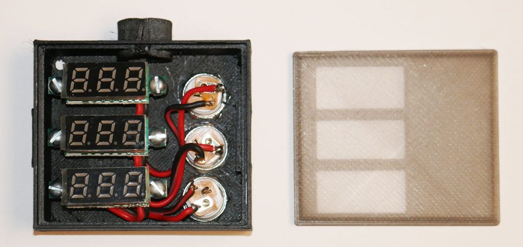
Into the cases, we installed voltmeters and connectors. The voltmeters are powered by the voltage under test, which is a bit odd but works for our needs here. Self-powered voltmeters eliminate the need for a separate power supply and ground loop risks. These voltmeters have an accuracy of +/-5%, but we were able to recalibrate them to better than +/- 2% accuracy.
3D Printed Voltmeter Assembly and lid
The bump on the top held a tripod mounting nut, but we ended up not using it. We made three of these. Each case interlocks to the next case.
Assembled voltmeters with early labels
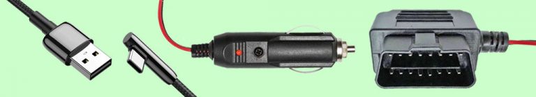
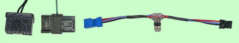
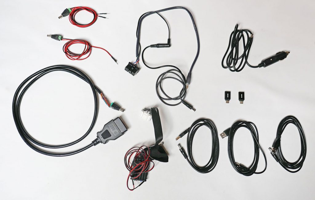
We bought and made a number of cables used to connect into different parts of the vehicle.
Assorted 12v and 5v cables
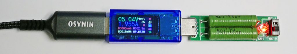
To measure the current handling abilities of the USB ports, we have a handy meter with a two-level resistive current load.
USB Load Tester
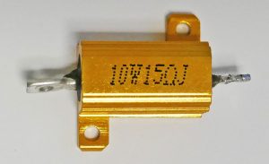
For measuring each 12v connection’s current, we used one or two 15-ohms 10 W resistors along with a current meter. The resistor gets hot very quickly, so we had to limit each test to about 35 seconds. While it may be possible to pull more current, most 12v accessories require less than 1 amp that doesn’t use the Power Socket connection.