This project creates a professional 12V always-on power tap for your dashcam that connects to the Tesla Model S intrusion module connector. For the 2021+ Model S LR/Plaid, which no longer has accessible headliner power, see our Power Tap alternative.
We include a few notes on the Model X, but this project will not work as written in the Model X. (Aug-2025 update)
- Introduction
- Intrusion Module
- Microphone Panel
- Connector Pinout for S and X
- Parts for Model S
- Tools
- Assembly
- Installation
There are many ways to make this connection, so this is just one way it can be done. The connectors we use match the Tesla connectors and are polarized so they can’t be inserted incorrectly. We added a T tap in the cable, which is used to power your dashcam. The design allows for easy installation or removal without any effects on your car (i.e., no car wires are cut or modified). Assembly takes about 30 minutes. Model S LR/Plaid vehicles manufactured in June 2021 and later do not have the connectors, so see our Power Tap for those vehicles.
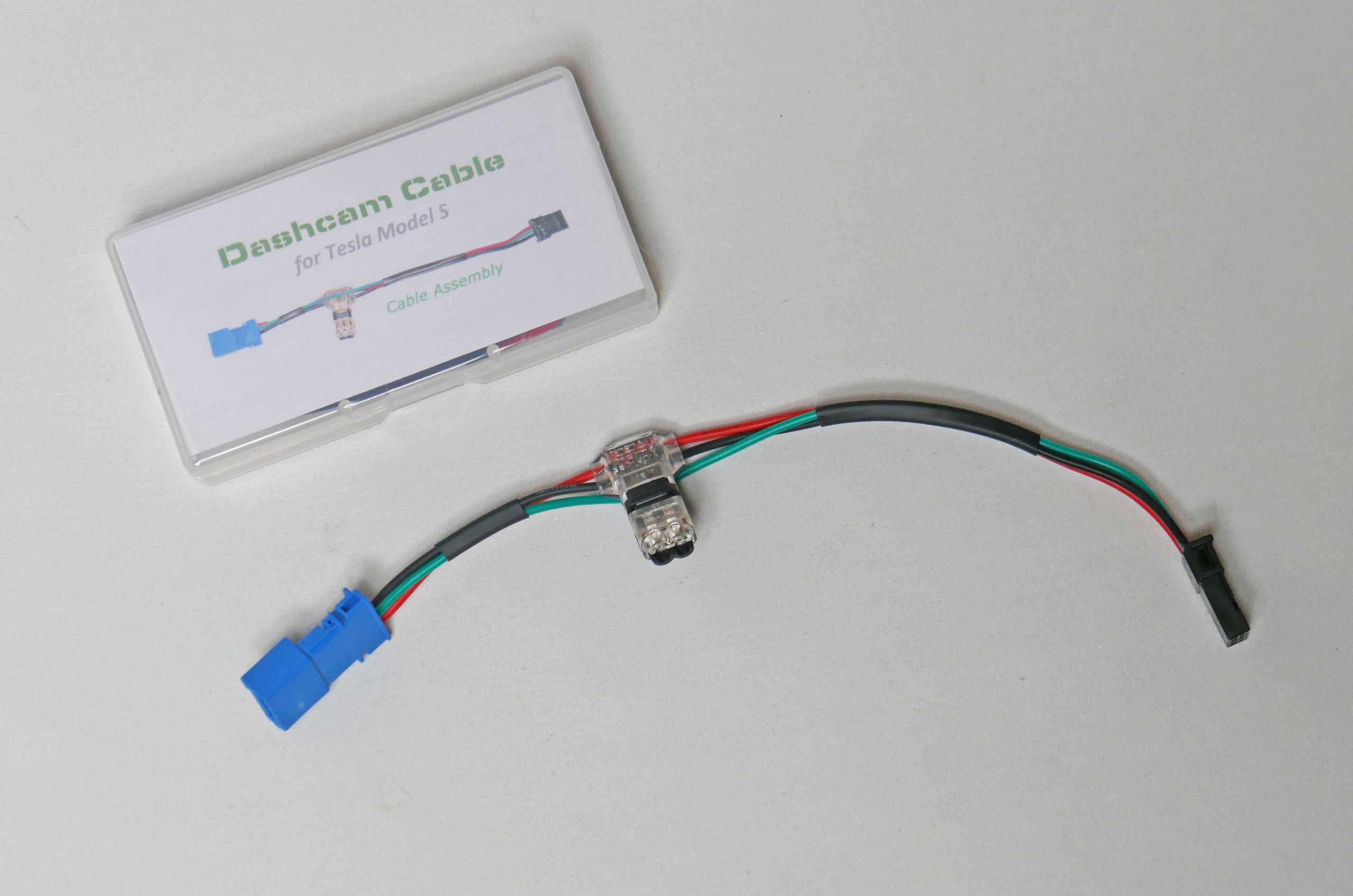
Built Dashcam Cable Assembly
The always-on connector is for the intrusion module. The module is included in European Model S cars. In North America, Tesla made the Intrusion module available as a retrofit for $350 in 2018. It includes a new microphone assembly, the intrusion module, installation labor, and a window decal. The car’s software is also modified to provide intrusion detection on/off control. We’ve designed our power cable to work with cars without or with the intrusion module, so long as the always-on connector is available (see next).
While this project is for the Model S, we believe all Model X vehicles include the intrusion module. It is a different design with a different 8-pin connector (but only 3 wires are used). On the Model X, the module is located next to the center dome lights. The pinout is shown in the next section.
The always-on power source is in the headliner, behind the microphone panel. To open this panel, pull down using your fingers at the back edge. Two snaps will release, and it will hinge down an inch or so, where you can then slide it towards the back of the car to release.
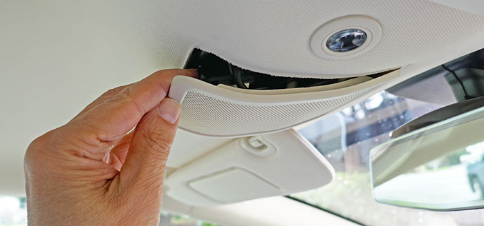
Opening the microphone panel
There should be a 4-pin, 3-wire black connector taped to the panel, or if your car has the intrusion module, the connector will be attached to that module.
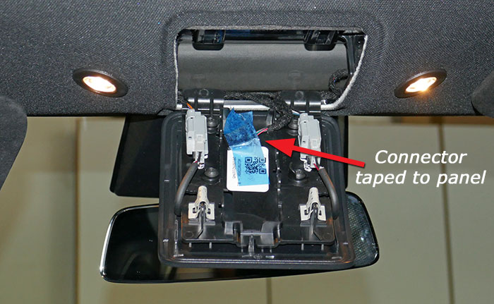
Connector attached to the panel with blue tape (yes this is a different car!)
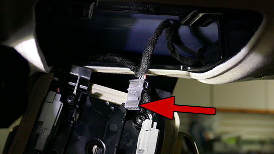
Intrusion module connector untaped
The 4-pin intrusion connector is black and has three wires. Don’t confuse this with the two gray microphone connectors. These do not have any power.
All Model S cars made after September 16, 2015, will have always-on power, and cars from 2012 through late 2013 also include always-on power, as do all European cars. Non-European cars made in 2014 and 2015 may not have the connector, or it may be taped up with the large wire bundle in the headliner and hard to extract.
Intrusion Module Connector Pinout Model S uses a TE Connectivity 4-pin connector
Pin 1: 12v, wire color: Red/Dark Blue (older cars and AP2 cars), Tan/Black (after Oct-2014, before AP2). We’ve also heard that one unidentified car had a gray wire!
Pin 2: LIN bus (do not use this wire), wire color: Light Green/Red
Pin 3: Ground, wire color: Black
Pin 4: Unused
Pin 1: Ground, wire color: Black
Pin 2: LIN bus (do not use this wire), wire color: Green
Pin 4: 12v, wire color Red/Blue
Pins 3,5,6,7,8: Unused
- 7 inches of 22 AWG high-temp silicone wires, red, black, and green or blue ($16 for five 26′ rolls)
- 1 T-tap connector ($12; package of 12)
- 1 T21 tap, only needed for 3-wire dashcams ($21; package of 20, not shown below)
- 1 TE Connectivity female housing 3-968696-2 ($0.53)
- 2 TE Connectivity female terminals 5-963715-1 ($9.60 for a strip of 100)
- 1 TE Connectivity male housing 1241634-1 ($0.44)
- 2 TE Connectivity male pins 1-928918-1 ($11.60 for a strip of 100)
- 1 4mm x 60mm heat shrink tubing or similar ($9 for a kit of various sizes)
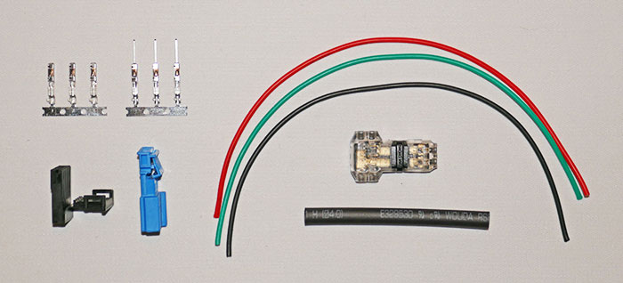
Project parts
- Pliers (to close T-tap connector)
- Wire stripper/cutter or similar
- Soldering iron and solder (optional)
- Heat gun
- Crimp tool or small long-nose pliers (many crimp tools will work, such as the low-cost one referenced, but the official TE crimp tool and die is more than $500)
For each wire end, strip about 3/32″ or 2mm of insulation from the wire. We then tinned the wire with a small amount of solder.
Using the crimp tool attach the male terminals to the end of each wire.
Even though the wire is crimped, it’s not all that secure. We elected to add a tiny bit of solder to each terminal and pin where the bare part of the wire is crimped. Add just enough solder so the solder flows and the tinned wire solder melts. If you add too much solder, the terminal or pin will not fit the connector!
Attached the male pins into the blue housing in the order shown – Red at the top, green next, and black last. The 4th position on the connector is unused. The pins only go in one orientation and should click when fully inserted. If necessary, use a tiny screwdriver to push a terminal into the clicked position.
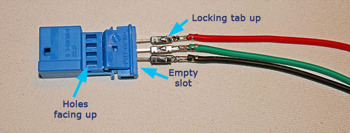
Pins partly inserted into blue housing
Check carefully that each pin is fully inserted, then push down on the locking part of the housing.
Cut 1/2″ or 1.2mm of heat shrink tubing and thread it on the three wires. Thread the remaining shrink tubing onto the wires. Do NOT shrink the tubing yet.
Heat shrink tubing inserted
Using the crimp tool, attach the female terminals to the end of each wire and solder.
Insert the three female terminals into the black connector housing in the order from the top, red, green, and black. Again, the last position is not used. Each terminal should click into place. If necessary, use a tiny screwdriver to push a terminal into the clicked position.
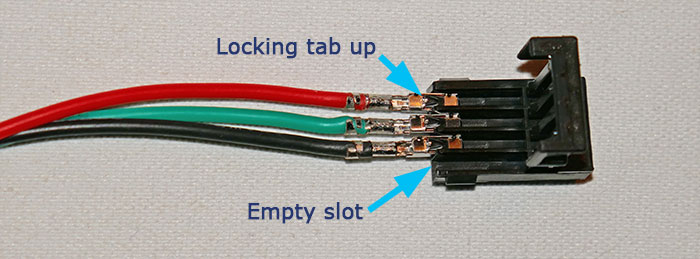
Terminals partly inserted into the black housing
With all the terminals fully inserted, on the black housing, close the locking tab.
Open the T connector and thread the red and black wires through the connector. Place the red wire in the top slot and the black wire in the bottom slot. Move the T connector so it is closer to the blue connector, so there is about 1.5″ or 4 cm of wire between the two. Use pliers to clamp the clear and black portion of the T connector together until it clicks.
The bottom of the “T” will be used to connect power to your dashcam. Check that it is not already closed. If closed, you’ll need to pry it open by releasing the two side tabs (not so easy).
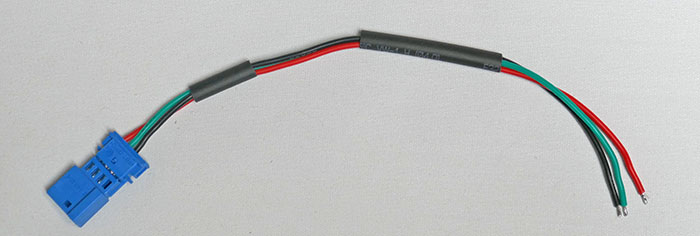
Using a heat gun, shrink the heat shrink tubing. Your completed assembly should look like this:
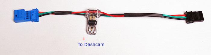
Completed assembly
Your dashcam hard wiring power cable should end in a red and black wire, and include an in-line fuse. For our installation, we used the wires from a BlackVue hardwiring cable (for most models from DR430 to DR900). This kit has a 15-foot power cable, which is too much wire to stuff into the headliner, so I cut it to length. Be sure to re-attach the in-line fuse. It’s best to do this work before the dashcam wiring is installed as described in our dashcam installation guide.
Insert the dashcam’s red and black wires into the two holes in the transparent portion of the “T” connector. In the cable view above, your dashcam red wire goes in the left “+” hole, and the dashcam black wire in the right “-” hole. The next images should help get this right. Make sure they are fully inserted and clamp the T connector together using pliers.
Connect your blue connector to the Tesla black connector.
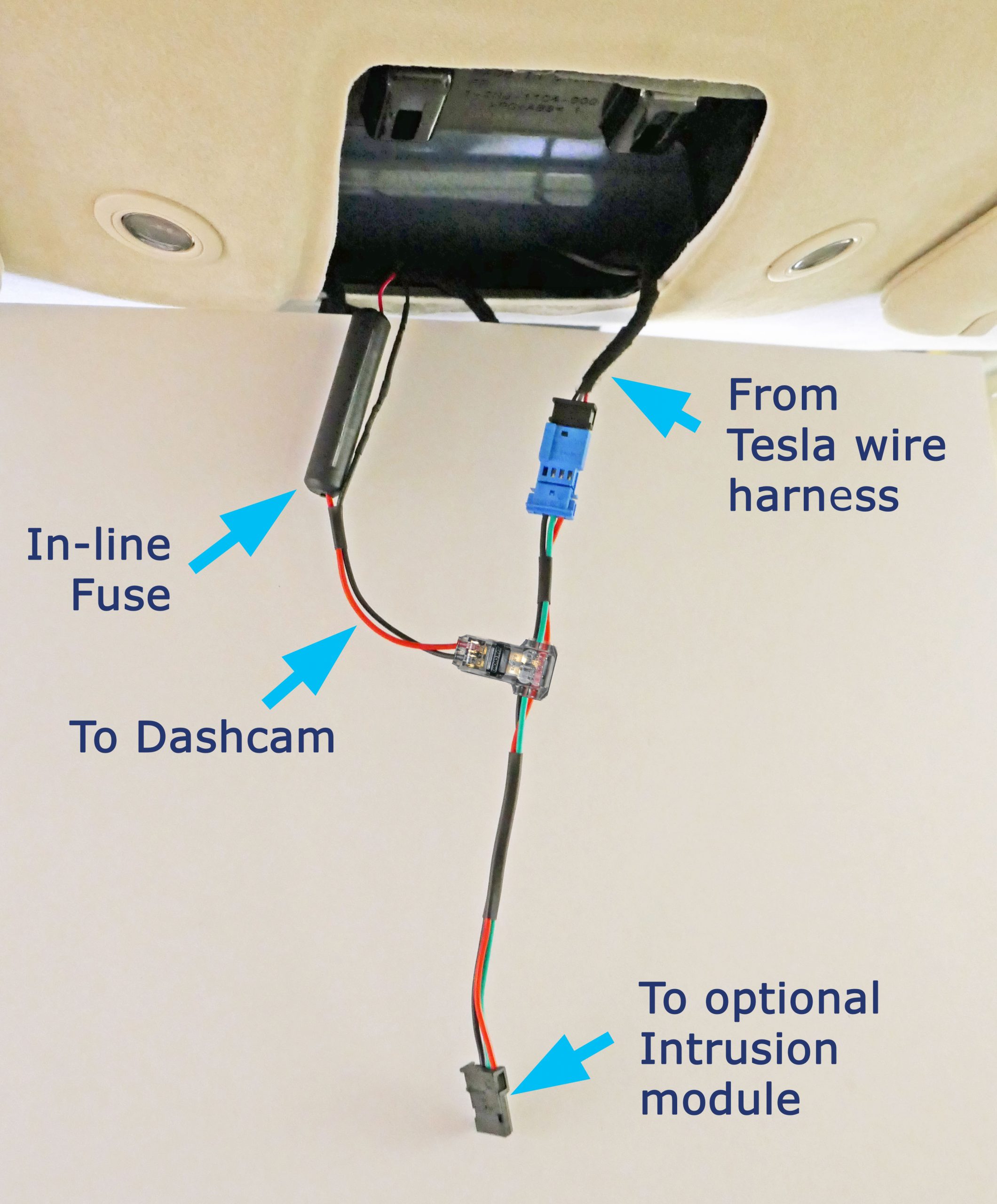
Cable in the car
In the view above, we placed white cardboard between the microphone cover and the assembly to make it easier to see the wires.
If your dashcam includes a third yellow wire, the wire is a second power wire which is provided for ICE cars where the dashcam would quickly drain the battery. For an EV, you can keep your dashcam powered all the time without any concern. The power drain is trivial compared with the EV’s total power. If there were no other loads, even a small EV battery would power the dashcam for years. Use the optional T21 connector (gray in the image) to combine the red and yellow wires together.
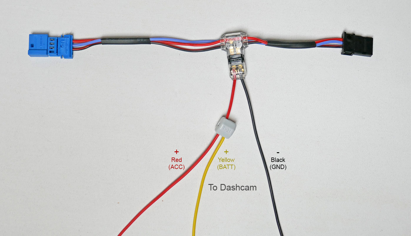
Connections for a 3-wire Dashcam
Test that your dashcam is getting power.
Poke the in-line fuse, the blue connector, and the T connector up inside the headliner. If you have the intrusion module, connect the black connector to the intrusion module.
Close up the microphone panel by sliding the front in first, and then pushing up until it clicks into place.
If you have the intrusion module, it is smart to test it as well. To do this, roll down a window in an area that is not too loud. Lock the car and wait about a minute with the key held 50 feet away or so. This arms the intrusion module. Without bringing the key back in range, insert your hands into the car and clap your hands loudly together. The alarm should sound. Use the FOB to unlock and silence the alarm.