As I stated at the start, this project is a bit crazy for the cost and amount of effort it took. It really started with a phone-based CAN bus analyzer I designed. This got bogged down as the off-the-shelf CAN bus products I tried couldn’t keep up with the massive amount of data Tesla produces on a single CAN bus, let alone the 4 busses I wanted to monitor. It works well when you limit the data (which is done at the hardware level), but I wanted it all.
I shifted gears to designing my own low-level hardware and writing my own code for the microcontroller. This is connected to the phone via USB. Bluetooth would never work for this, as it is way too slow. I then found the phone itself was also unable to process the massive amount of data coming in, store it and display the data in different ways in real-time. This was not going the way I wanted! During this time, a few other owners introduced products with limited CAN bus recording with offline processing. I may revisit that project as the phones/tablets gain more power. I only need that Intel i9 18 core extreme CPU that lasts longer than a few seconds on a cell phone battery!
I got the idea for Tshow when the refresh Model S came out, as it had the perfect display area behind the front T-badge. I could reuse some of the hardware and software work I’d previously done as Tshow is far less demanding. Meanwhile, a new microcontroller with dual CAN bus hardware appeared late last year, which was perfect for this project. I didn’t need all four CAN buses, but I did need two (CAN 2 and CAN 3) for monitoring data for the Refresh S. With the Plaid, only one CAN bus needs to be monitored.
With the analysis of CAN bus traffic, I identified critical ids to track for the various features. Here are the key IDs I track for Tshow for a Plaid Model S. It applies to the 3/Y and Plaid Model X as well.
| CAN BUS | ID | Byte(s) | Bit(s) | Function |
|---|---|---|---|---|
| Vehicle | 0x118 | 2 | 5-7 | Vehicle State |
| Vehicle | 0x129 | 2 &3 | Steering Position | |
| Vehicle | 0x212 | 1 | 3-5 | Charging State |
| Vehicle | 0x318 | 0-5 | Date and Time | |
| Vehicle | 0x33A | 6 | State of Charge | |
| Vehicle | 0x3E2 | 0 | 3 | Headlights On |
| Vehicle | 0x3E2 | 2 | Left and Right Turn Signals | |
| Vehicle | 0x3F5 | 0 | 4-7 | Hazard Status |
Here are the IDs I track for Tshow for a Refreshed Model S. It may apply to older models as well, but I never confirmed it.
| CAN BUS | ID | Byte(s) | Bit(s) | Function |
|---|---|---|---|---|
| 2 | 0x203 | 1 | 6 | Emergency Flasher |
| 2 | 0x209 | 2 | 6 | Left Blinker On |
| 2 | 0x20A | 2 | 6 | Right Blinker On |
| 2 | 0x238 | 2 | 3 | Headlights On |
| 3 | 0x00E | 0 & 1 | Steering Position | |
| 3 | 0x116 | 3 | 4-6 | Vehicle State |
| 3 | 0x222 | 0 & 4 | Charging State | |
| 3 | 0x302 | 1 & 2 | State of Charge |
To include day/night brightness and holiday features, I needed an accurate date and time. Unfortunately on the Refresh, I was only able to find the date/time broadcast on CAN bus 6. Since I didn’t want to add a third CAN bus to the project, so I used the processor’s built-in RTC along with battery backup. I wrote the code so the time and date are automatically set when the app connects to the processor. For Plaid, the vehicle CAN issue regular time and date values, which are used to automatically update the RTC every second.
I built the prototype on a breadboard, which makes it easy to try out different processors and design ideas while creating the companion Android app.
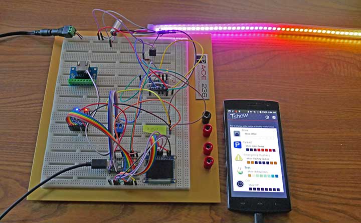
An early breadboard test
As the project rolled along, I concluded PCBs would be necessary to ensure reliability and compactness. That meant learning the latest schematic and PCB software. Of course, I made a few mistakes and had to re-run new boards. This is no different than most engineering projects (although costly for a one-off project).

Processor PCB version 2
Version 2 still had a couple of minor errors, and the remote control’s NeoPixels data was unreliable on longer cables. I added a second differential bus transceiver and fixed the errors on the version 2 board. The version 3 PCB and schematic include these changes.
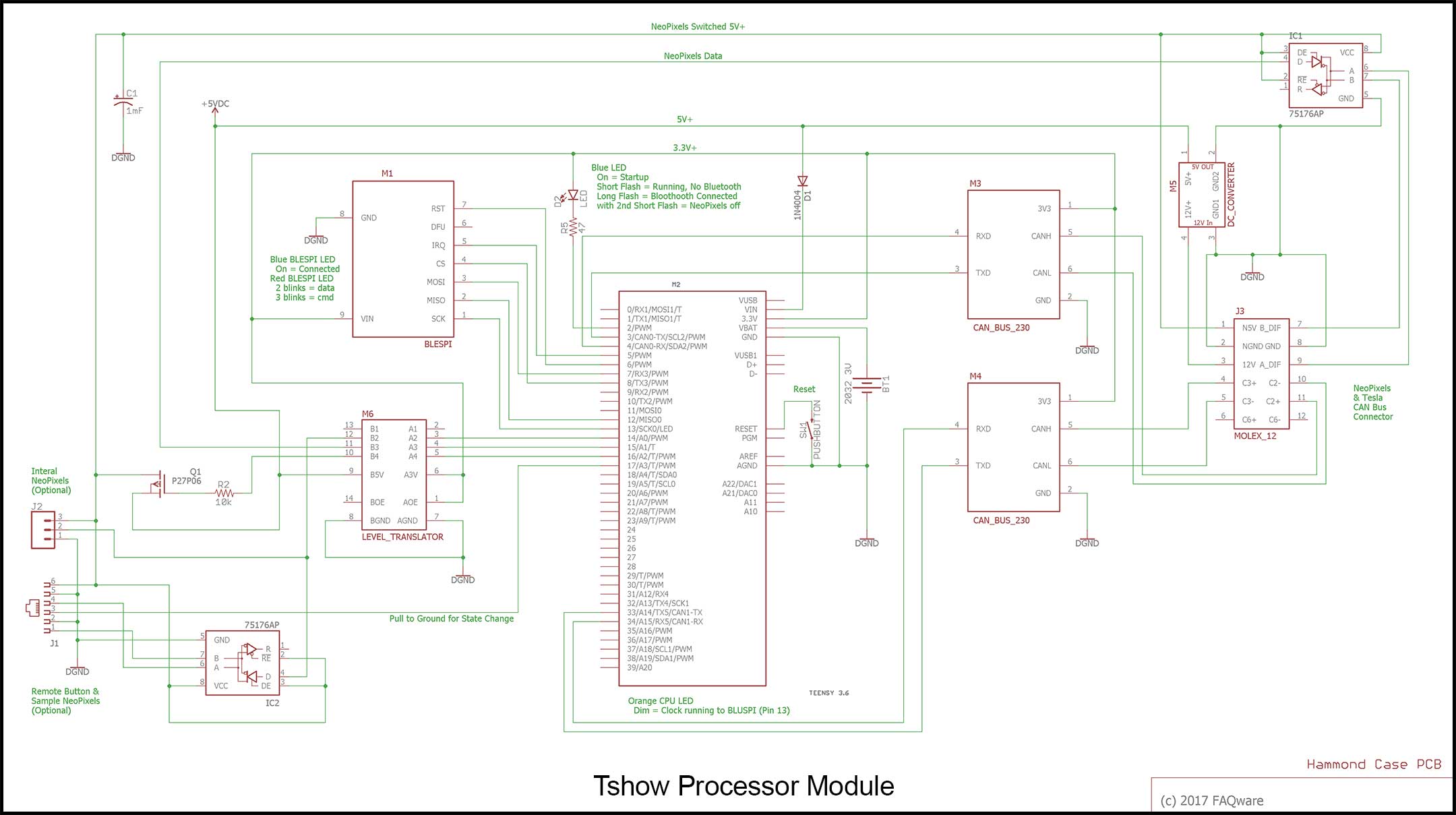
Processor Schematic (version 3, click for full size)
A few sharp engineers may notice I used some modules rather than surface mount ICs. Surface mount parts are difficult to solder for a one-off project and these specific parts are only available in surface mount. Luckily, there are modules available with the surface mount ICs, that are only slightly more expensive than the IC itself. They do take up a little more PCB board space, but not enough to matter.
The NeoPixels use a single serial data line. This becomes unstable for longer runs, typically over 12″. By using differential transceivers, the signal is not affected by wire length. The processor module connects to the receiver and remote via a differential connection, which in turn connects to NeoPixels.
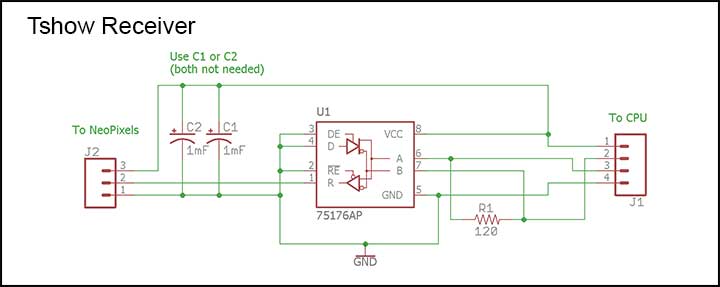
Tshow receiver schematic
The receiver needs mounting on the T-badge assembly very close to the NeoPixel input. I found the desired mounting on the passenger’s side physically interfered with the radar module, so in a last-minute decision, mounted it on the driver’s side and flipped the NeoPixels so the start (i.e. pixel 1) was on the driver’s side to keep the wire run as short as possible between the receiver and the NeoPixels data input. This required a fairly significant software change to “flip” the visual direction in various display modes.
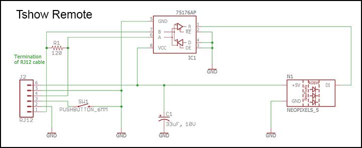
Tshow remote schematic
Along the way, I couldn’t find a suitable plastic box to house the remote unit. I got the brilliant idea to make a 3D box for it – having never done so before! This required learning a new CAD system – Tinkercad. It took 3 tries to get it right, but the design improved dramatically with each iteration. With that under my belt, I had planned to use a stock plastic box for the receiver, but a 3D box would be so much better. I got a good box design after two tries. For those who have never done 3D design, the tools today are quite impressive. Once the design is complete, I used an online service to choose a fabricator to make it, often in 2-3 days. Printing each box in ABS costs under $20. In the last iteration, I combined both boxes into a single print.
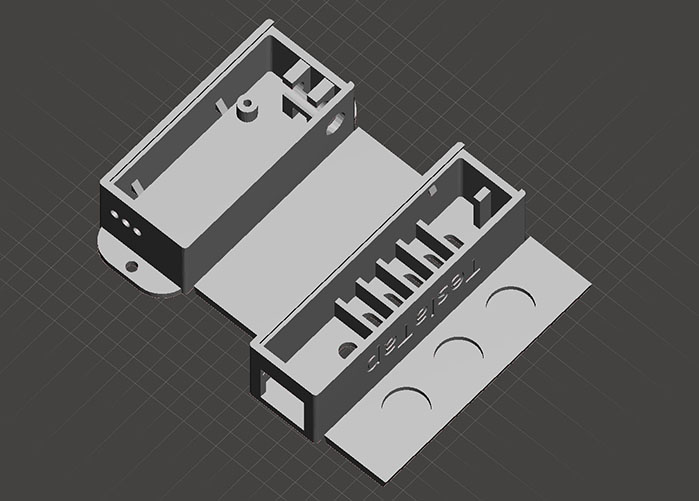
3D view of receiver box and lid (top), remote control box and lid (bottom)
My one regret at the time was not making a 3D box for the processor unit. I rectified that with the Plaid design. It saves quite a bit of rework on the stock plastic box.
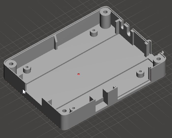
3D Main Box Design Bottom
With Plaid, I added two additional connectors. One OBD-II female connector provides access to the vehicle CAN bus. This has nothing to do with Tshow. I also added a tiny 1.27″ OLED display via an RG45 8-pin connector.
The first Tshow did not include any secondary display. With Plaid, I added this display to resolve some CAN bus values and assist with code debugging. I added a few interesting vehicle values too. The display is too small to see while driving, and the OLED is too dim to see in bright daylight. Worse, at higher cabin heat levels (100°F?) the display fails. Clearly not automotive grade!
OLED Display Module
This table shows the hand-wired connections, as this was added after the PCB was designed.
| Function | OLED Display | Teensy 3.6 Connections |
|---|---|---|
| Ground | Pin 1: G | Pin: GND |
| +5V | Pin 2: + | Pin: +5V |
| Chip Select | Pin 7: OC | Pin 10: CS |
| Reset | Pin 8: R | Pin 0: RST |
| Data/Command | Pin 9: DC | Pin 9: DC |
| Serial Clock | Pin 10: CL | Pin 13: SCLK |
| Micro Out/Serial In | Pin 11: SI | Pin 7 MOSI |
I wrote the microcontroller software using the Arduino IDE, in C++ code. While the Teensy 3.6 processor can run at up to 192 MHz, I run it at 120 MHz as more speed is unnecessary and it reduces the power consumption slightly. I wrote the Android software in Java using Android Studio. As such, it may not be easy to port to Apple iOS. Not something I’ve investigated. Android devices such as a 5″ quad-core phone with Android 6.0 and Bluetooth 4.0 can be had for as little as $50 and will work great with this project if you don’t already have an Android phone or tablet