3 – 18” wires, 20 gauge, stranded, in Red, Black, and White (or any 3 colors)
1 – NeoPixel RGBW Strip, 144 pixels, 1 meter, white strip (later this is cut up)
4 – Silicone caps
1 – Tube, GE clear silicone II (important, do not substitute, some silicones use acids that will destroy the copper traces!)
You’ll see in the full-length 144-pixel strip at the 72-pixel mark, the two LEDs are slightly wider apart than anywhere else. Cut the strip into two 44-LED strips, starting from that center point.
Important – the direction of the strips is one-way! There are little arrows printed on the strip to help show how the data line is connected as it goes from one Pixel to the next.
Arrows printed on NeoPixel show input and Output
Wire the two strips in the center together with short wires (< 1”). At the same time also attach two 18” longer leads to the two power leads. Also use the silicone caps, with the wires poking out the end of the caps. Seal both caps with GE silicone. On the output end of one strip, put another cap and seal it. On the input end of the other strip, solder the 18” white wire to the input line and run it through a cap and seal the end. When complete the strips should be watertight.
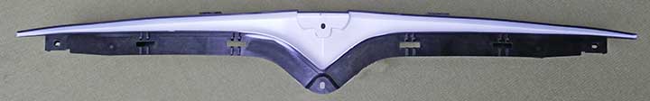
1 – Tesla T-badge front support* Refresh: Tesla P/N 1062472-00-E; Plaid: Tesla P/N 1611024-00-B
1 – Tesla T-badge – Tesla P/N 1056386-00-F*
1 – Screws M5-1.8 x 14 mm – Tesla P/N 1006533-00-A*
1 – Polycarbonate 30” x 4” x .062” thick, 50% transparency, smoke grey (Grey #1730 )
1 – Receiver Module (from earlier)
1 – Waterproof 4-pin connector male end, ~7” long (comes with the cable)
2 – NeoPixel strips/assembly (from earlier)
2 – Screws #2 x ½” metal screws (black/stainless preferred)
1 – White spray paint -satin finish, for plastic (high reflectivity desired)
1 – Blue painter’s masking tape
* These parts can be removed from your car, but obviously it is not great to drive with a partly disassembled for the few days it may take (with drying time) to modify these parts. I purchased the parts from Tesla for about $40 so I could take my time, and only pull apart the car once.
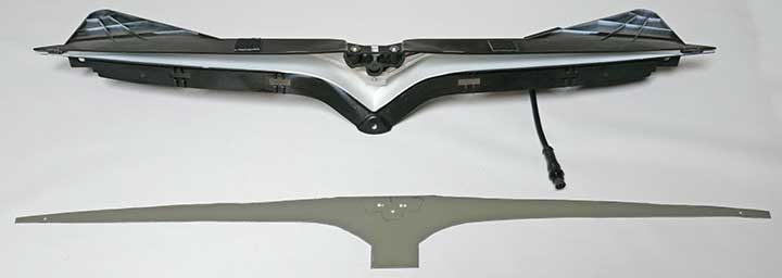
Refreshed T-Badge assembly back, T-Badge and uncut polycarbonate sheet
Cut a scrap of wood to about 20” long by 4” wide and ½” thick (size is not critical). In the center of the wood mount the Tesla T- badge upside down, using two T-25 M5 14mm taped screws (Tesla PN 1006533-00-A). Inset the screw heads into the wood so the bottom is flush. Run the badge through a table saw to cut it in half right at the cut line so the portion of the badge with the mounting holes will be flush with the front of the “T-Badge” assembly. I used a thin kerf 40-tooth combination blade and cut through it slowly to avoid melting. Unmount the mounting section from the wood. You’ll be left with the chrome badge portion I reference as “T” and the black plastic mounting section I’ll call “M”.
To prepare the front support, I masked off the edges and spray painted the inside with white paint. Next, attach the black plastic mount “M” to the front support using the two Tesla screws. Confirm it is flush with the front of the support.
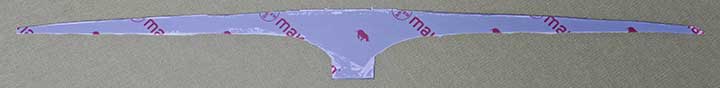
Refreshed Painted Assembly before “M” part mounted
From the back, there is one hole for a screw. On the chrome portion, you should see an indent where you’ll drill to receive a new 6mm x 30mm tapping screw (not the one Tesla uses). Insert a screw and adjust the T-Badge on the support so it is centered. I used two more screws so the badge does not turn and is better supported than just a single screw. Drill holes above the main screw and to the sides to hold two more 6mm x 30mm tapping screws. Disassemble the chrome badge and put it aside for now.
Position the two NeoPixel strips into the T-badge support temporarily. With another scrap of semi-flexible translucent plastic, drill and attach the scrap in the center to hold the center of the strips in place and add a little angle to the strips in the center. The strips can’t be twisted too much, but I could get about 30 degrees of twist for better center illumination. Note that the input end (with one wire) is on the right so the wire will be near the receiver module.
“M” part mounted and center NeoPixels mounting
Note where the LEDs end within the channel. They should be flush with the front (i.e. not protruding). I marked this about another ¼” or so towards the ends with a silver marker. I cut two small ½” 2mm thick sections of scrap plastic so that they fit in the channel, are about ¼” away from the LED end, and will be flush with the front. Remove the LED array. Epoxy each plastic scrap at the marks you indicated so there is still room for the LEDs. These will be used later for a tapping screw to hold the polycarbonate diffuser onto the front of the assembly.

Closeup of one end with epoxied insert
The entire front of the support will be covered with a polycarbonate diffuser to keep bugs out and protect the LEDs. This is far easier to clean than the deep channel of the T-Badge support. It will not be watertight but should keep the inside area clean.
While I used a 30” x 3” diffuser, in hind-sight, I’d use a 30” x 4” size to start with. I made a stiff cardboard template for the opening (I used carbon paper, which was clunky, but works). The template should completely cover the opening, and at the center bottom, goes down below the center hole. In my pictures, the 3” wide didn’t quite go down to this hole. The template should not cover any of the rectangular openings. Plaid uses a slightly different design and the top edge butts against a plastic lip. I actually transferred the cutout I originally made for the Refreshed S part to the new Plaid part.
I then transferred the template to the polycarbonate on the side with an all-white protection film (no logos). Using a sharp utility knife, run it along the lines about 3 times. Then use plyers to break apart the waste part of the design. Careful not to stress/crack it, especially on the center bottom inside curves. I used more than 3 slices with a knife in this area.
Polycarbonate cut to size, with protective film on both sides
Placing the polycarbonate flush over the support channel, drill two holes near the ends into the epoxied plastic fillers. These are used for two metric 4 x 10mm self-tapping metal screws. In the center drill through the polycarbonate for the 3 holes that are used to secure the T-Badge. Mount the T-Badge and the two end screws as a test. It should hold the polycarbonate flush with the front of the support.
On my polycarbonate, one side has a frosted protection film, and the other side protection film with some logos on it. I removed the logo protection layer but left the frosted layer attached. This will remain on the inside to diffuse the LED light. For Plaid, where I was reusing the same plastic, the protection film was starting to peel. I remove it, applied a layer of 3″ wide thin double-sided clear adhesive tape, and then applied a 0.1mm white plastic diffuser. Both the tape and the diffuser were stuff I had laying around, so I have no idea of part numbers or where to get them. You may have to improvise your own diffuser.
Disassemble the T-badge, polycarbonate, and NeoPixels. Drill three holes for the power and data wires in the back of the support. Remount the NeoPixels feeding the wires through the holes. Mount the 3D printed receiver box, and drill additional holes to feed the wires into the Receiver box. Feed the wires through the 3 small holes in the receiver box, and solder them to the PCB (marked as +, data, and -). Note the Refresh and Plaid have the receiver box and holes in different locations.
Feed the open end of the male waterproof connector cable/stub through the large hole in the receiver box. Use a small tie wrap to secure the cable, but leave it loose for now. The 3D box is designed with a path for the tie-wrap to hold the cable tightly inside the box. Solder the 4 wires, red to plus, green to “A”, yellow to “B” and blue to minus. Fit the board in and secure it with at least one screw. Pull the tie wrap tight, ensuring it will not interfere with the lid. Slide the lid in place. Before installation on the car, I suggest doing a bench test once the other portions of the project are completed to confirm it all works as expected and fix any problems encountered.
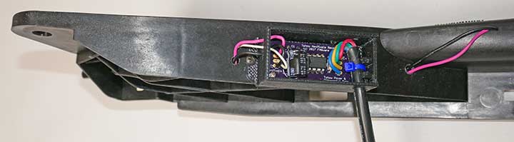
Refreshed back of assembly with receiver box mounted and connected, lid not attached
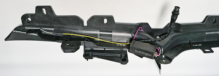
Plaid back of assembly with receiver box mounted and connected
Refreshed front of assembly and drilled polycarbonate sheet
Attach the polycarbonate and the T-Badge. Since the LEDs are watertight, it is not necessary to make the support watertight, and it may be wise to leave it partly open to let any moisture accumulation and rain that might enter drain out. I sealed the entire top between the polycarbonate and the support with a bead of silicone since that is the area that is likely to get rainwater while driving. I also sealed where the wires exit the support and enter the receiver box.
The support has two mounting tabs on the far left and right. To make the fit consistent, you need two washers to extend these by the thickness of the polycarbonate. I made two washers using scrap polycarbonate. I drilled two holes in the scrap and then cut them to size. I epoxied each “washer” in place. I made a third washer for the center hole, but you shouldn’t need this if you started with a polycarbonate sheet that was 4″ wide and acts as a washer.
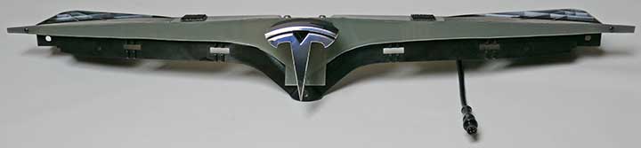
Refreshed T-badge completed assembly (similar to Plaid)
3 comments
First off, thanks so much for the work to put this project together, and then the time spent posting it for other’s benefit.
Alas though the other sections are very clear to me, I have read the above a couple of times and can’t quite figure out one thing. I noted from earlier in the instructions that some pictures which might be helpful aren’t provided, but hoping you can elaborate on the below more such that I can picture what was done from my experience dismantling this trim.
“In the center of the wood mount the Tesla T- badge upside down, using two T-25 M5 14mm taped screws (Tesla PN 1006533-00-A). Inset the screw heads into the wood so the bottom is flush. Run the badge through a table saw to cut it in half right at the cut line so the portion of the badge with the mounting holes will be flush with the front of the “T-Badge” assembly.” – What exactly is being sliced in half. It reads to me as if the T is being cut, but can’t see that in any provided pictures, nor any other part pictures.
As I did this about 4 years ago, I don’t have any additional pictures to share. The 3rd picture shows the back of the cut-off T-logo which may help. Sorry I don’t have more to go on.
Ahhhhh. The T supporting frame is cut, not the T cut in half from the front, so it can go in front of the diffuser, without requiring weather-tightness-affecting cutouts to have the stock mounting method of the T go through the top of the diffuser. Got it!