While not necessary, it is smart to test the system before installation, in case there are any issues. To do this, you’ll need to make several test cables and have a 12 VDC power supply. Parts can be substituted as desired.
1 – Power Supply, 12 VDC, 3 amps
1 – RJ12, Phone cord, 6 wire (length unimportant)
1 – Molex mating 12-pin Female connector #34729-0121*
6 – Molex female crimp terminals #34803-3212 (sold in a string of 100)*
1 – 6” of 2 conductor wire, 20-22 gauge
4 – 1 Wire, 22 gauge stranded, 1-2” long each
4 – Shrink wrap tubing, 1/8” diameter, ½” long
1 – Easy Connector female/DC power adapter jack (to attach to the power supply)
1 – Waterproof 4-pin connector female end, with ~7” long cable
* available from Mouser Electronics
It is almost impossible to stick an 18-gauge wire into the Molex connector, so you need to add pigtails to the 4 wires. On the open end of the 4-conductor cable, solder the 22-gauge pigtail wires and cover with the heat shrink tubing, and shrink. Crimp a terminal to each of the pigtails and optionally solder the wire to the terminal.
The Molex connector has slot numbers labeled as the top row 1 to 6, and the bottom row 7 to 12. Look carefully so you use the right slots. It is almost impossible to remove a terminal once clicked in place. The terminals only go in at a single orientation, with the bottom row terminals 180 degrees from the top row. You can use unused slot 6 or 12 as a test with scrap wire and terminal. The picture below from Molex may help too.
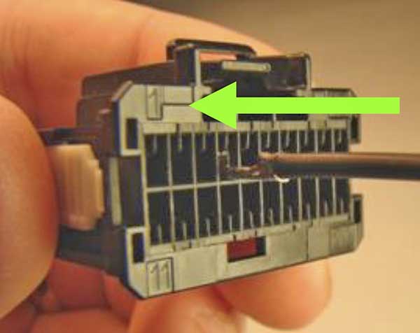
Example orientation of female terminal into a Molex 20-pin housing (we use a 12-pin housing)
For the 4-wire cable stub, insert the terminals into the following slots: Red to pin 1, Blue to pin 2, Green to pin 7, and Yellow to pin 9.
Take the 2-conductor wire and crimp a terminal to each lead. On the other end, strip ¼” of insulation and tin the exposed wire. Attach the two power wires to the Easy Connector. Insert the plus lead terminal (as marked on the Easy Connector) into pin 3 slot, and the minus terminal into pin 8.
Important! Carefully inspect your work when done to make sure the right slots are used and the polarity is correct. On the Molex connector, seat the white locking cover in place.
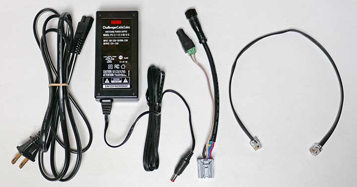
Power supply and test cable and short 6-wire phone cable
RECOMMENDED: If you used headers to attach the Teensy CPU, Bluetooth module, etc., you may want to power it up without these attached and without any NeoPixels attached. With a meter, verify the +5v is working at the DC/DC module output when you supply 12v power. Note that the NeoPixel 5v power will be off until the Teensy is connected and powered up. Power down, and insert all the modules. Test again and see the orange LED lights on the Teensy and the red Bluetooth light flashes.
With power off, connect the T badge light assembly to the 4-pin connector, and power up the 12v. If the software is not loaded, connect a PC to the USB connector and load the software from the Arduino IDE. It is safe to have both the 12v and 5v via USB at the same time. It is also safe to connect the USB only (no 12v) and the Teensy will be powered up (but little else).
With the software loaded, it should start and cycle through the startup where all LEDs are lit in white, then red, green and blue and then switches to the last state (typically off). Remove the 12v power.
Connect the remote control using the RJ12 cable. Confirm the cable is not “twisted” in that pin 1 on one end of the cable must connect to pin 1 on the other end. This is the standard way the cable should be built, but sometimes they get it wrong. It may not matter for phone use, but it matters for this project.
Apply 12v power. Confirm the remote’s NeoPixels match the main display during the power-up sequence. Use the button to rotate through the different states. The Remote shows a mini-view of the main display.
If the A-Diff and B-Diff connections are swapped, the NeoPixels will stay off or perhaps light up in yellow or all white. This causes no harm, but it indicates the two diff wires are backward.
After the power-up sequence (about 5 seconds) The LED on the Teensy Processor should be a dim orange, showing the clock being sent to the Bluetooth module. The Bluetooth module has two LEDs. The blue LED is on when connected to the App. The red LED will blink three times every second indicating it is in command mode (normal). Occasionally it may blink twice, indicating data mode.