1 – Uxcell Battery holder for CR2032 Cell (10 pcs)
1 – Lithium-Ion Battery, CR2032
1 – Electrolytic Capacitor, 1000 uF, 10v
1 – Diode 1N4004
1 – LED, T1, Blue
2 – 75176AP, Differential Bus Transceivers
1 – RJ12 Jack, Low-profile 6-Pin
1 – Molex 12-Pin Connector, Male, #34691-0120*
1 – Adafruit Bluetooth Module, BLESPI, with male headers
1 – Adafruit CPU Module, Teensy 3.6, with male headers
5 – Short female headers on 0.1” centers, 36-pin (will cut to size)
2 – SN65HVD230, Can Bus Transceiver Module, with male headers (only 1 needed for Plaid)
1 – CPT 12 VDC to 5 VDC Converter, 15W
1 – TXB0104, 4-bit Level Translator Module
1 – P27P06, P-channel MOSFET 60V, 27A
1 – Resistor, 10K ohms, 1/4W
1 – Resistor, 47 ohms, 1/4W
1 – Grayhill Pushbutton SPST, PCB mount, #38FSP9B9M6RT*
1 – Tshow Mainboard, Printed Circuit Board (zip file, Gerber)
1 – Hammond Plastic Case, 1555F2F17GY* (or use our 3D printed case)
1 – Paper adhesive label, 3.4” x 3.2”
4 – Screws to mount PCB to the enclosure
2 – Screws, 3/8″, self-tapping, to mount CPT DC-DC converter to PCB
4 – Velcro squares 1” x 1” or similar
4 – Double-sided carpet tape, cut to 1”x1” square
* available from Mouser Electronics
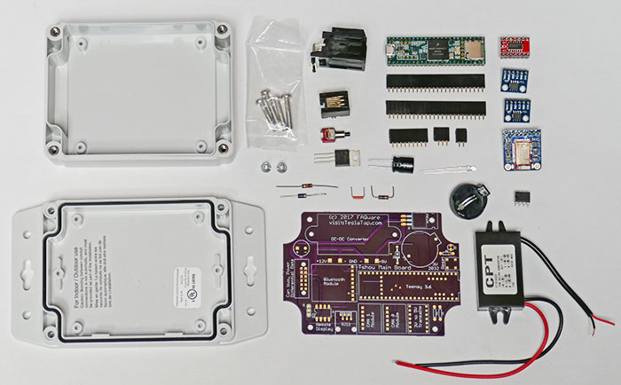
Processor parts before assembly
Using the Tshow mainboard, assemble and solder all the parts. I started with the DC/DC converter, using two 3/8” long self-tapping screws to hold it in place.
On some parts, such as the Teensy CPU board, I soldered male headers on the Teensy and used female headers on the PCB. You’ll need two 24-pin headers for the long sides of the Teensy, and the 5-pin header near the Teensy program button. The extra 9 holes near the USB connector are not used. The Bluetooth module will need a male header, with a female header on the PCB to provide clearance for the IC under the module.
The female headers are probably not necessary, but it makes debugging far easier if something is not working right. The LED should be side mounted so it will poke out from the enclosure in the same direction as the reset button.
On the CAN bus modules, you need to remove the 120-ohm surface mount termination resistor. You can desolder it, or perhaps break it off with longnose plyers. The Tesla CAN bus already has the necessary termination resistors. For the Plaid/3/Y only CAN 0 Module (labeled on PCB) is needed. CAN 1 is only needed for the Refreshed S.
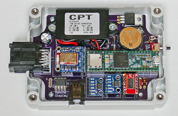
Assembled Processor PCB
For my first design, I used an off-the-shelf grey plastic box that requires some modifications and holes. I mounted the completed PCB assembly at the top of the box (without flanges). You’ll need two holes for the reset button and LED. Two rectangular holes are needed for the two connectors. I also made a partial opening for the USB port so I could load new software when the case is open.
The bottom of the grey box will need a partial cut for the smaller connector. The larger connector needs a much larger cut, including part of the mounting tab, which must be cut away. Most of these cuts I made with a table saw, which makes for a clean cut. I’m sure there are other ways to do this work.
With Plaid, I made a new 3D printed box that is thinner and overall is a better design. The 3D printed box includes cutouts for an optional OBD-II connector for debugging and/or using a Bluetooth adapter with an app like Scan My Tesla. It also has a cutout for an RJ45, which I hard-wired to the PCB for an optional OLED display.
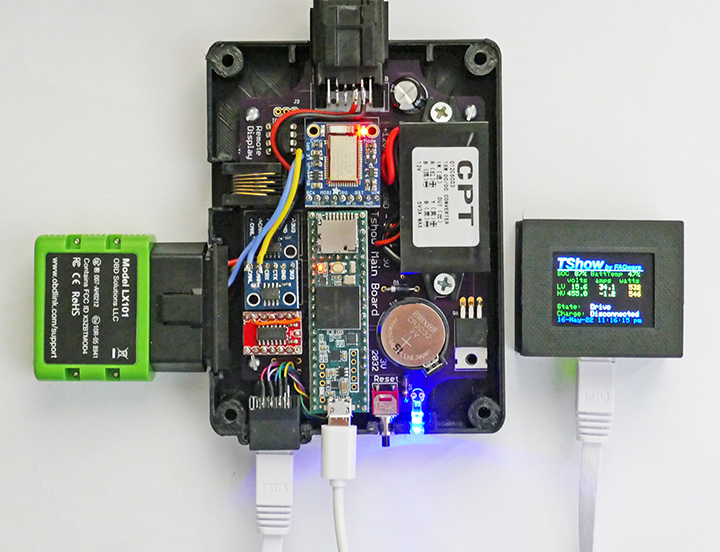
Using 3D printed box with OBD and OLED
The project also used some PCB modules that basically are just a surface mount chip. This avoids having to solder a surface mount chip to the PCB. The cost difference is negligible but does require some additional soldering.
This processor module label can be printed on adhesive paper and cut to fit the indent on the top of the plastic box.
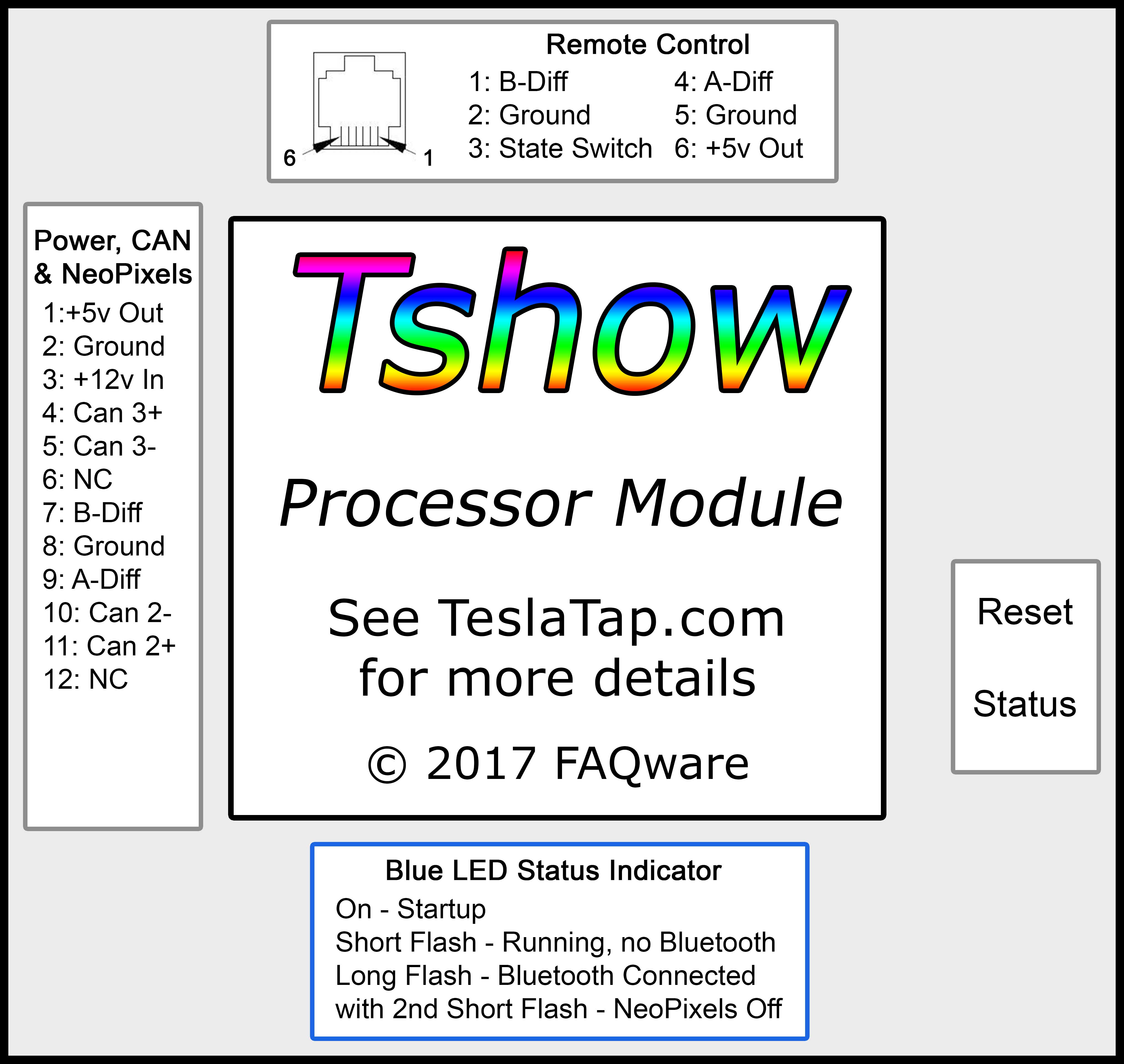
Processor Module Label (click for full size)
The box is screwed together with four screws, included with the box.
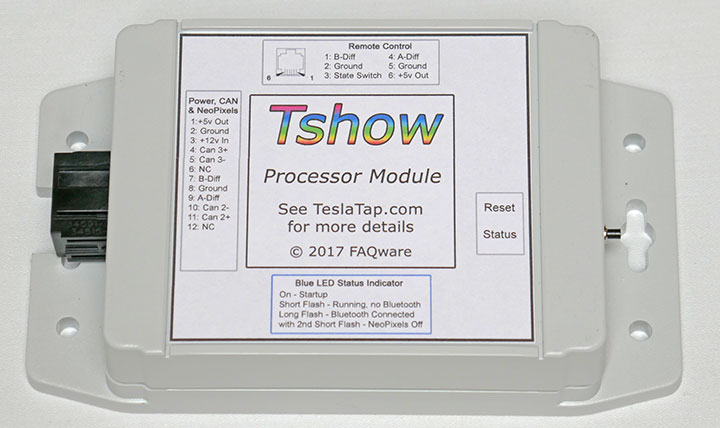
Original Completed Processor Module

New Completed Processor Module
2 comments
Am I missing a link to download the Tshow Mainboard, Printed Circuit Board to be sent to one’s favourite PCB fabricator?
Now included in the parts list.