There are a number of ways to improve trunk lighting. You could replace the two existing LED modules with brighter ones. Our Footlight LED Enhancement page goes into great detail – either modify the modules or buy new ones from a third party. We think our custom design specifically for the Model 3 is a much brighter solution.
We elected to go with a custom design that dramatically brightens the trunk area with an array of LEDs that cast fewer shadows and improves the color rendition of the trunk lighting. No cuts or holes are needed to install this project, and it can later be removed without any effects to your car.
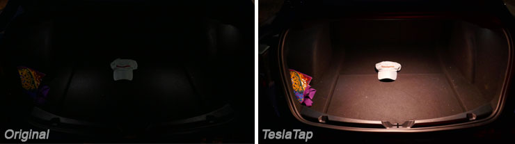
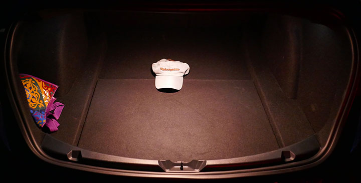
Before and after photos were taken with the identical manual camera settings.
We also created a plastic hardware-free LED mounting lens. While you could mount the LEDs with the strip adhesive on the back of the LEDs, they tend to fall off in high heat typically encountered in vehicles.
It’s hard to buy only the parts necessary for this project. We’ve tried to source the smallest quantities, but there will be some excess. You may be able to replace some parts with those you have on hand. The minimum order of all the parts is $198 plus about $20 in shipping. This results in some excess, as it is hard to buy the exact quantity needed. Assembly after the parts are acquired should take about 45 minutes and installation typically takes 5 minutes.
- 1 TT 3D printed LED mounting bracket (See below; using 3DHubs, ~$15 or to print yourself HD glass filament reel $52 for 360 grams)
- 1 TT 3D printed rear cover (optional)
- 4″ LED Strip, with 12 super-bright LEDs, CRI > 90, 3000K, 12VDC, high-density ($34 for 5 meter reel)
- 3 feet 22 AWG high-temp silicone 2 conductor wire, red/black ($18 for 82 feet)
- 1 TE Connectivity Automotive connector male 1-1534155-1 ($0.62)
- 2 TE Connectivity Automotive connector male pins 1-928918-1 ($11.60 for a strip of 100)
- 1 TE Connectivity Automotive connector male cover 1-1534027-1 ($0.43)
- 1 TE Connectivity Automotive connector housing female 1-1534113-1 ($0.34)
- 1 TE Connectivity Automotive connector female latching clip 1534112-1 ($0.64)
- 2 TE Connectivity Automotive connector female terminals 5-928999-6 ($0.36 for 2)
- 1 T-tap connector ($12; a package of 12)
- 1 Aluminum bar, 4″ x 1/2″ x 1/16″ ($26 for 48″ long, at Home Depot)
- 2″ long Thermal tape, 10mm wide ($10 for 25m roll)
- 1″ long Foam double-sided tape, 3/8″ wide x 1/16″ thick ($15 for 50-yard roll)
- 1 Vishay MB6S-E3/10 Diode Bridge, surface mount ($17 for 100)
- 1 heat shrink tubing, 1 mm x 5mm
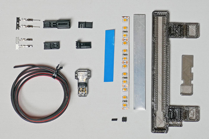
Most Parts for the Trunk Light
- Crimp tool or small long-nose pliers
- Pliers (to close T-tap connector)
- Wire stripper/cutter
- Soldering iron and solder
- Scissors
- Hacksaw or metal shear (for the aluminum bar)
- Flat screwdriver (to pry Tesla LED module out)
- Heat gun (to shrink heat shrink tubing)
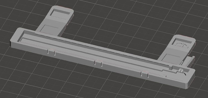
We designed a mounting bracket that protects both the car and the LED strip. It also looks great, but that’s a minor feature for this application. Download the STL files Model 3 Trunk LED V6. and the optional cover Model 3 Trunk LED Cover V6
Any 3D printer than has a heated bed should work to print this part. For the filament, we used HD Glass PETG in translucent black. Other colors such as transparent or transparent white may work, but we did not try it. Do not use PLA as it will deform under temperatures encountered in your car. ABS has an even higher temperature rating, but it can be more brittle and has some nasty fumes when making it. Printing was done at 300 μm layers, no support, and no raft. It consumes about 10 grams of material. Your printer may require different settings depending on the filament you use. For our printer, it took a little under an hour to print the two parts.
If you don’t have a printer, you can use 3Dhubs to find someone to make the bracket for you. A quick check appears the large part can be made for less than $15, depending on the quality. Ideally, you want a printer that doesn’t require a raft, but there is no way to specify that in 3Dhubs.
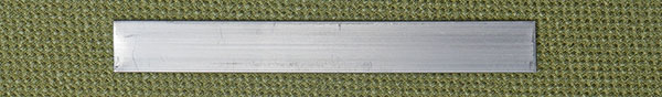
Cut the aluminum bar heat sink to 4″ long. If the edges are sharp, file them down.
We need to add some thermal double-sided tape to ensure the LED ends do not short out on the aluminum bar. Attach the thermal tape, about, 5/8″ on one end and 3/8″ on the other. The 3/8″ should slightly overlap the end.

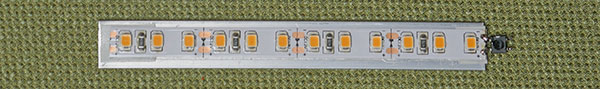
Cut the LED strip, about 4″ long, Remove the blue thermal tape backing, and remove the tan backing tape on the LED strip. Attach the strip to the aluminum bar, such that the end with the minus marking (-) is up and the right side is about 1mm over the right end, and the LEDs are centered.

We will attach the diode bridge to the end of the LED strip. Here is the diode’s pinout:
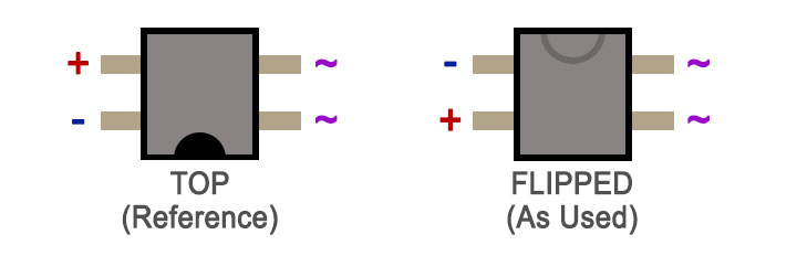
The half-circle indent identifies the top diode bridge orientation and is hard to see. I used a silver sharpie pen to make it clearer. You’ll flip the bridge over before attaching it to the LED strip. Orientation is important, or it will not work in the wrong orientation!
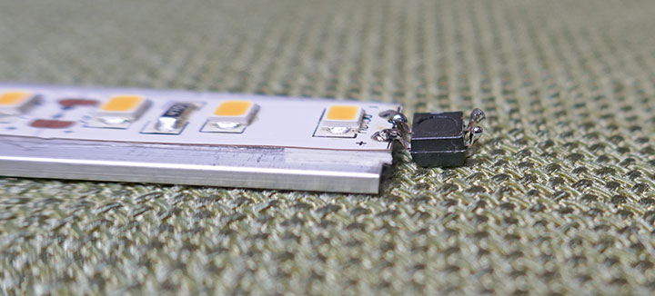
Side view of the diode bridge and LED strip
Cut the wire into two sections, one 4″ long and the other 32″ long. With the 32″ section, on one end, of the two wires cut one wire 1/16″ shorter and remove 1/16″ insulation from both wires on that end. Insert the shrink-wrap on the longer wire. Solder the two wires to the end of the diode bridge. It doesn’t matter which color (red or black) connect to the diode bridge input (marked as ~ above)., The wires should come off at a sharp angle. Move the heat shrink tubing over the connection and shrink it with a heat gun.
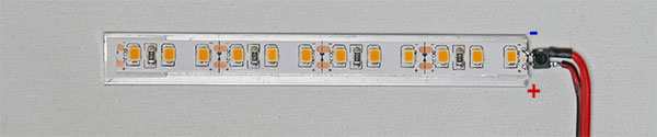
Flip the aluminum heat sink and LED potion, and feed the other end of the 32″ wire through the small hole in the 3D printed mounting bracket, being sure not to twist the wire. Then snap the aluminum heat sink and LEDs into the bracket.
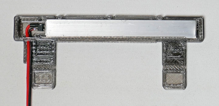
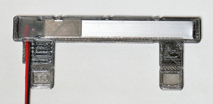
Optional to protect the connections: Add 7/8″ long thermal tape to the left-back of the aluminum heat sink. Insert the final 3D printed rear cover part.
On the 4″ section of wire, strip about 1/16″ of the insulation off of each wire on each end. Tin each lead with a light amount of solder (optional). The orientation is important! Look at the image to orient the terminals (left) and the pins (right) with the black and red wires. Use a crimping tool (if available) or use long-nose pliers crimp onto the wire. I elected to solder each wire to the terminals as well (optional).
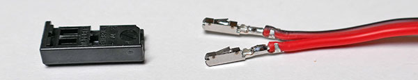
Female terminals with housing orientation, positive/red on the smooth side of the housing
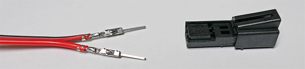
Male pins with housing orientation
Insert the pins/terminals into the respective housings, be sure to use the correct polarity. In the center of the 4″ section use a knife to split the two wires apart for about 1″.
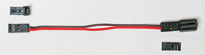
On the male housing (left), slide the larger locking cover onto the housing. On the female housing (right) slide the thin cover onto the housing. If the clip or cover is not installed properly, the connector will not fit!
Install the T-connector as shown and clamp down to lock it into place. You may need pliers to lock the t-connector. The polarity and color of wires through the T-connector is not important.
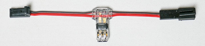
With the LED assembly, get the unconnected end of the 32″ wire. Split the wires apart and insert them into the T-connector and clamp it down to lock it into place. Polarity is not important here either.
Attach double-sided foam tape in two places on the LED assembly (the blue protective tape is left on for now). The sides are each about 3/8″ long.
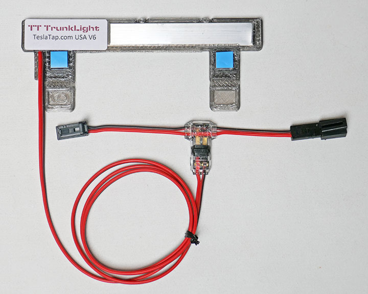
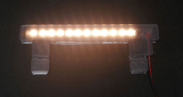
Completed (purchased) assembly
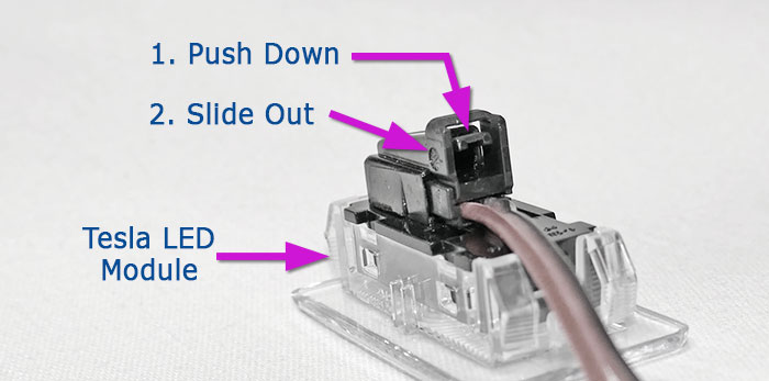
In the Model 3 trunk, remove the left side Tesla LED module. You can use a screwdriver to pry it out, as there is an indent on one side. It helps to press from the back of the LED module to pop it out. Remove the connector from the LED module – it has a retaining lock that must be depressed before the connector will release. Even with depressing the retaining lock, sometimes it requires a screwdriver to pry it out.
Testing (optional)
For those who bought the fully assembled units, we fully test each unit before shipping and additional testing is unnecessary. For those building their own, it’s smart to test the assembly before installation.
Temporarily connect your new TT LED assembly between the wire harness and the original Tesla LED module. Confirm the original Tesla LED module lights and the new module also lights up properly. Disconnect the module from the wire harness and the original Tesla LED module.
Lighted module (dimmed to photograph)
Problems
If one or both lights are not working, the polarity is likely wrong on one of your connections:
| Issue | Solution |
|---|---|
| Neither Tesla or your new TT LED assembly light | The female connector is wired backward and the diode bridge is installed incorrectly |
| Only the TT LED assembly lights | The male connector is wired backwards |
| Only the Tesla LED module lights | The diode bridge is installed incorrectly |
Final Installation
In the roof of the rear shelf, there should be a wide black plastic cover. On some of the very early Model 3s (Q1-2018 and older), this cover is missing, and you’ll need to ask service to order and install it first.
Remove the blue protective tape from the adhesive pads on the LED assembly. Pry the cover down slightly and insert the LED assembly in the center of the trunk shelf. There are two groves in the assembly that will fit into the lip of the cover. When positioned correctly, press the assembly up so the adhesive pads presses on the metal area.
Route the wire behind the black cover over to the Tesla LED module on the left (drivers) side. At one point it is fairly tight. Do not leave the wires pinched by the cover.
Feed the wires with connectors out of the LED hole. Connect it to the wiring harness and the LED module. Confirm it is working. Insert the Tesla LED module back into the opening so that it snaps into place.
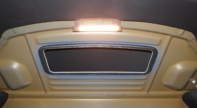
Looking upwards from trunk floor with the TT LED assembly installed
If you have the trunk open for an extended time, the LED power may be turned off by the car’s software. If this occurs, close the trunk and reopen it.
We’re really pleased how much it improves the lighting. Our first units are still working fine after more than a year of use. Still we were not totally satisfied with that early design and made a number of improvements over the year. Our current v6 design improved thermal and electrical aspects and should last for the life of the car.
Trunk Light Project Completed