While this is project is shown for a Model S, it should be applicable (with minor changes) to other model’s trunk area. (May-2021 update)
This project takes about 60-90 minutes and the cost of the parts is $30-70 (the LED strip cost is the big variable). You may want to read through all the instructions to see if you feel up to doing this project and look at the result photos at the end.
You’ll need the following set of parts to do both sides. There are many ways to do this project, but we’ll outline the way we did it. You can improvise and/or elect to do it differently, or just do one side.
- Left and right 3D Printed frames (see below)
- 4 Self-tapping screws, #6 1/2″ long, flat head
- 2 Six-inch lengths of strip LEDs non-waterproof, 60 or 120 LEDs/m, 12 VDC (cut from the longer strip). There are many vendors, lengths, LED density, and color choices at eBay, Amazon, and others. There are quite a few cheap LED strips that will work depending on your budget. Most are in 5 meters (16.4 ft) reels, so they can be used for other projects too.
- 1 Solderless Wire Quick Splice Connector – 18-22 Gauge – 25 Pack

- 2 6′ Male 2.1mm Plug to Female 2.1mm Jack CCTV Power Cable – We’ll cut this to provide the wire and a barrel connector pair. Note: I did not buy this specific cable, but it looks as if it’s a good choice.
- 2 pieces heat shrink tubing, 1/2″ length by 1/2″ diameter, preferably marine shrink wrap (has a soft glue inside).
- 1 set of Single Color LED strips Quick Connector to DC – 4 pack (only 2 are needed, optional if not soldering, see text)
- 2 tie-wraps, black, small
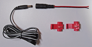
Connectors, solderless connectors
This approach requires printing two frames. These make the project look really professional and solve the problem of the strip LED adhesive failing over time.
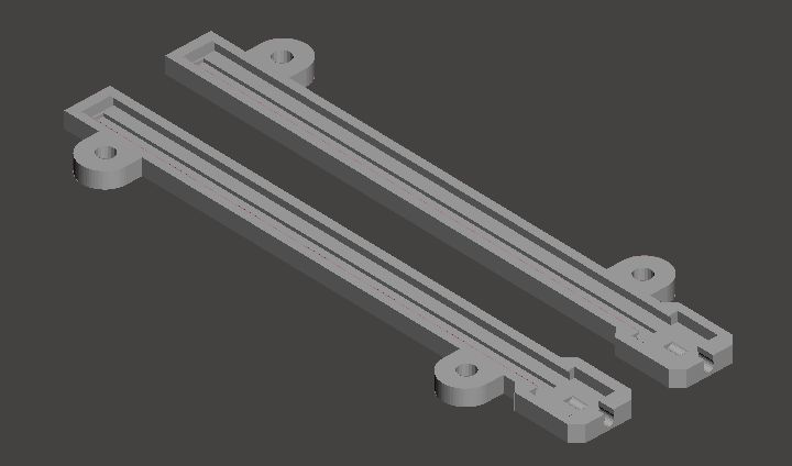
3D Parts to hold LED strips
For plastic, avoid PLA, as it may warp in high heat. We used PETG and ABS should work too. You can go with transparent, but we elected to go with a smoke color. The specific material we use is HDglass Transparent Black.
You can make it yourself, or use a service such as Hubs. A quick check found parts at 200 μm layer height using PETG Transparent or Transparent White for under $10. The cost went up to $17 for a higher quality of 100 μm layer height parts. Either should work fine. Other specifications – use 100% infill and no support is needed.
File size: 65 KB
- Soldering iron
- Electrician’s fish tape (strongly recommended to pull the wires)
- Pliers (to close the solderless connectors)
- Portable Drill
- 7/64″ drill bit
First cut the power cable, with the female end having about 3″ of length (this is the connector end that is mostly covered in plastic). With the female connector portion, you’ll need to connect the wires and connector to the LED strip.
You should have a quality soldering iron, designed for electronics work. Solder the red or white marked connector wire to the + mark on the LED strip. Solder the black wire to the – mark. If you make a mess of it, just cut another 6″ LED strip and try again. You should have lots to work with. Cover the connection with the heat shrink tubing and shrink the tubing either with a heat gun or lighter (be careful not to melt the wires or LED strip). While still hot, mash the heat shrink tubing flat. The head shrink serves as a strain relief.
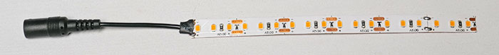
LED strip with connector
Slide each LED strip into one of the 3D printed frames. Do not remove the adhesive protection on the back of the LEDs – it will remain in place. The wire can be pushed into the slot at the end of the printed part.
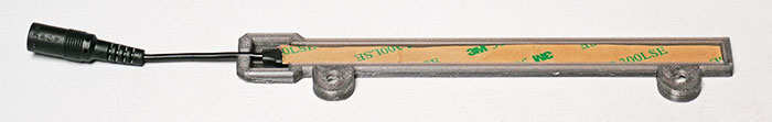
Completed Module – LED strip inserted into part- looking at the backside
Now you’re ready to work on the car. While likely safe, I suggest NOT having the charger plugged in. You may be working close to the charging port, so it’s best if it is not energized. It’s rather well protected, but why take a chance.
We’ll cover the passenger side, as the driver’s side is basically the same (you can choose either one or do both). Remove the bottom Tesla LED Assembly. Cars built after about August 2013 will only have these LED assemblies if you purchased the premium lighting package. Fortunately, the wires are still available on one side, but more difficult to get to. Thanks to Akikiki who worked this out. If you do not have the side LEDs, see the comments section below for further instructions to get to the wires.
For those with the LED assembly, it snaps out fairly easily with your fingers. There are two wires attached, and it likely will only come out about 2″. If you want, you can disconnect the Tesla LED assembly from the wires. You have to depress the locking clip and slide the connector out from the assembly.

Tesla LED Assembly
Feeding the wires through is the biggest pain of the project. We strongly recommend using an electrician’s fish tape, a thin flexible spring steel tape that has a plastic nub and hole on the end. I’m sure there are alternatives, but I doubt a coat hanger or string can be made to work and you don’t want to scratch up the metalwork. Another alternative is to disassemble the side parts, but it doesn’t appear this is easy either (and we didn’t try).
With the fish tape, feed the tape through the LED mounting hole up to the large hole. You need to start the tape between the carpet/plastic liner and the metal frame. Don’t push it through the metal hole or you’ll never get it. Your objective is to feed the tape up to the larger hole in the carpet/plastic liner. You’ll only see the larger hole if you look up at the side from the floor of the trunk. It’s not normally visible.

Tesla LED assembly removed and sliding fish tape up through the hole
It’s unlikely the tape end will appear on many attempts. Two suggestions – one mark the length (about 2 ft) on the fish tape so you know when the end is about in the right location. I found it was channeled up close to the trunk opening, and digging your finger through the big hole towards the driver’s side of the car, I was able to catch the end and pull it out. By the way, I tried many times to feed the tape from the large hole down to the small LED hole, but could never make it, so I don’t suggest trying this alternative. With the tape passed through, knot the wire end of the remaining 5ft or so of the connector you cut earlier to the tape end.

End of fish tape out of top hole and wire knotted to end of the tape
Pull the tape and wire back so the barrel connector is left hanging out of the large hole near the parcel shelf rail, and the wire end is ready to be connected to the existing Tesla LED assembly. You’ll likely have far more wire than you’ll need, so you may want to cut it down (but leave 4-6″ extra). You can dry-fit the LED and connect it to the cord to see how it fits and the wire length.
Looking at the two wires from the Tesla LED assembly, there may be some wrapped electrical tape around the wires. You’ll need to remove some of this to use the wireless connectors. If cutting it off, be very careful, as you don’t want to nick the wires. Next using the wireless connectors, connect the white wire to the red Tesla wire, and the black wire to the black Tesla wire. There is not a lot of room to work with, but it’s not too hard. Leave at least 1/2″ of wire as shown before the black Tesla LED connector, or the LED assembly will not fit back on!

Quick connections
Reconnect the Tesla LED assembly to the black connector. Move your FOB near the driver door to turn the lights back on (if the lights are out) and with the Tesla LED light on, connect the new 3D printed LED module to the connector to verify it’s working and the connections are good (and the right polarity).
If the new LED module does not light, either a poor connection was made, or the polarity is reversed. Pull lightly on your new wires attached to the red quick-connector. If you didn’t push the wire fully in before clamping it closed, it may pull right out indicating a bad connection. If so, redo the connection (it splits apart easily). If the connections seem good, verify the polarity by checking the wire colors and/or using a meter up at the connector near the LED strip. If you prepared two strips, try the 2nd strip as perhaps one of the LED strips was wired backward. Rewire as needed.
With the 3D LED module confirmed working, push the wireless connectors and Tesla LED assembly back in the hole until it clicks in place. Temporally disconnect the LED module. Remove the parcel shelf if not already removed.
Position the LED module under the parcel shelf rail, with the two tabs pointing away from the trunk, but not obstructing the existing rail screw. Drill two holes for the screws. Mount the LED module with the two self-tapping screws. Connect the power. Duplicate for the other side.

Module completed on the right side (highly photoshopped to make it clearer)
Now enjoy your new lights! The night photos below give you a rough idea of the final results with and without the lights, and with and without a lighter carpet.

Old vs. New Lighting on Black Carpet

Old vs. New Lighting on Grey Carpet
Photo brightness was adjusted in Photoshop to better reflect real views. Grey carpet is Lloyd’s ULTIMAT in 137 Euro Grey. The lights are not on while driving, so they have no effect on the range. The light strips used here consume 2.2W per side (4.4W total).