This guide shows how to add FM or FM/XM to a vehicle that has been or is being upgraded from MCU1 to MCU2. The issue is caused due to the radio in MCU1 cars having the audio sent to MCU1 in analog form and is controlled via the CAN bus. MCU2 requires the audio, in digital form, and control signals to be sent via ethernet from a new digital radio. (Feb-2024 update)
- Summary
- Parts List
- 3D Printed Cover
- Recommended Tools
- Installation before or after MCU2 Upgrade
- Removing the Radio Module
- Analog Radio Details
- Digital Radio Details
- Wiring Diagram
- Cable Assembly
- Cable Routing
- Provisioning the Radio
- Contributors
Originally, according to Tesla’s service, it was not possible to make FM/XM work with the retrofit, but we are not convinced. It makes sense that Tesla didn’t want the extra cost and labor to replace the radio with a new one as it is not a simple process, but we expect it can be done with anyone willing to spend some DIY time with your car and with a little help from Tesla.
Since we wrote this, Tesla has offered a radio upgrade that includes the new digital radio, a special harness, and labor for $500. We recommend going to Tesla, which wasn’t an option when we created this retrofit. For the DIYer, here is what you will need:
- Purchase of the MCU2 compatible digital radio. There are different radios as noted for the USA market. See below for part numbers. We will also test if the very similar Model 3 digital FM radio will work in a Model S. The M3 tuner requires a bracket and some minor physical modifications.
- The existing antennas will work fine. Tesla uses the same antenna connectors between the S/X analog and digital radios.
- Purchase the parts for the connectors, terminals, and wire
- Create a new radio harness to connect power and data to the new digital radio.
- Replace the radio and install the new harness.
- Provision the car to recognize the FM or FM/XM radio [This is the hardest step – see below]
Here are the latest Tesla part numbers for the upgrade and radios. In the USA the current radio cost (any S/X version) is $225.00. it should be noted that Tesla’s policy is to not sell a specific part for your car that does not match what was originally on the car. For example, if you don’t have UHFS/Premium sound with the Subwoofer, they will not sell you the Subwoofer. What this means is if you have FM only right now, it is unlikely they will sell you the FM/XM tuner. For that matter, they may not sell you the digital tuner at all to replace the analog tuner. Note that the catalog states “No sale restriction”, but you may get pushback from the Tesla parts department. Hopefully, when you explain that the radio is required to make FM work with the MCU2 upgrade, they may relent. You can also scan the used market like eBay, but we’ve not seen any show up over the last few months.
| Description | Part Number | Notes |
|---|---|---|
| MCU2 Upgrade (includes labor & MCU2) | 1582613-00-A | Tesla service only |
| Radio, FM/HD, Model S | 1143703-00-C | No sale restrictions |
| Radio, FM/HD/XM, Model S | 1143711-00-C | No sale restrictions |
| Radio, FM/HD, Model X | 1143705-00-B | No sale restrictions |
| Radio, FM/HD/XM, Model X | 1143716-00-C | No sale restrictions |
| Radio, FM/HD Model 3 | 1079749-00-D | Unconfirmed if works in S/X |
| Wire Harness | 1453427-00-B | Came out after we first wrote this |
| Description | Part Number | Notes |
|---|---|---|
| Analog radio connector, male | Molex 34690-0160 | |
| Digital radio connector housing | TE Connectivity 2302475-2 | Not stocked 🙁 |
| Digital radio terminals, female | TE Connectivity 2-1703930-1 | 4 needed |
| MCU2 connector housing | MOLEX 34791-0040 | Ethernet |
| MCU2 terminals, female | MOLEX 560023-0550 | 2 needed |
| Wire, 24 AWG, twisted pair, shielded, high-temp, aircraft wire* | M27500-24SB2T23 (eBay) | 12″, for power |
| Wire, 24 AWG, twisted pair, shielded, high-temp, aircraft wire | M27500-24SB2T23 (eBay) | 48″, for ethernet |
| Spiral Wrap, wire protection | 1/4″ outside diameter | 7″ |
| Heat shrink tubing | 2mm diameter x 15mm long | 4 pcs |
| Tie wrap for 3D cover | 8″ or longer | 1 pcs |
| 3D printed cover (see below) | STL file V9 | optional |
| LED, blue, flat top | T-1, high-brightness | optional |
| Resistor | 10KΩ, 1/8 W | optional |
| Dual Fakra car radio antenna adapter | Dual Adapter (Amazon) | Only for M3 tuner |
Cable Purchase
Buy the Tesla wire hardness, or you can make your own. All the parts and details on how to make one are here. Note that the digital radio connector is very hard to source, so if you embark on this project, get that part first. The other parts are easier to obtain.
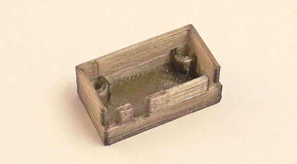
Not needed if you buy the Tesla harness. The analog radio connector is only available in a PCB mount style. In some ways, this is easier to connect to, but the rear pins are exposed. I’m sure there are many ways to cover these pins. We elected to make a 3D-printed cover that press-fits onto the rear of the connector. As a bonus, since the material we chose is translucent, we can install an LED on the back of the connector to confirm the connection is working. It consumes a negligible 1 mA when the car is powered up.
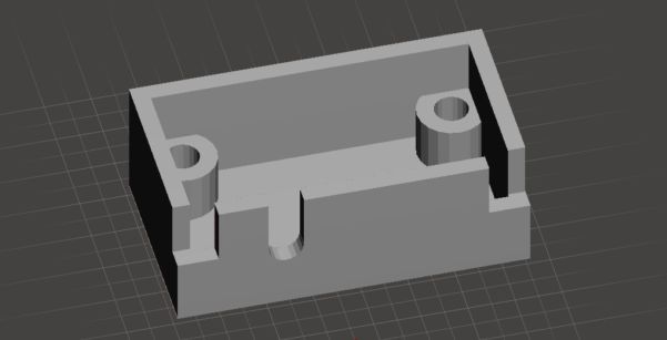
3D printed cover design
For the 3D print, we use PTEG filament, which is suitable for higher-temperature environments, such as the vehicle cabin. Do not use PLA, as it will warp and melt if the cabin gets too hot. We used Formfutura TransBlack HD Glass filament, with the bed at 80°C and nozzle at 225°C, 0.2mm layers, and 100% fill with supports. Plenty of other higher-temp filaments may work fine too, but we’ve not tested any others. Use our STL file V9 to make the 3D print. Once printed, you’ll have to physically remove the excess support.
If you don’t have a printer, you can use 3Dhubs to find someone to make the cover for you. A quick check shows that the part can be made for less than $20, depending on the quality.
For the radio replacement
- Hex bit type screwdriver or power screwdriver
- T20 bits, short and long shafts
- 10mm socket
- 12″ or longer socket extension
- Socket driver
- Midget ratchet with shallow depth for tight spots
- Auto trim removal toolset
For making the cable
- Soldering iron
- Crimping tool
- Diagonals
- Wire stripper
- Longnose pliers
- Heat gun
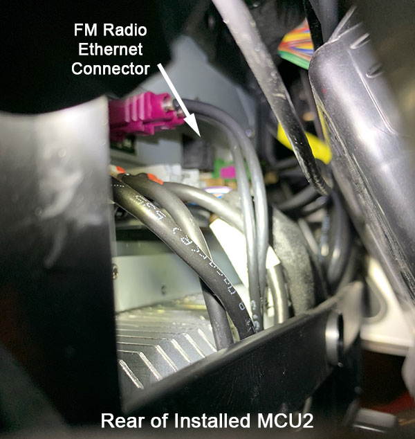
One difficulty with this project is connecting the FM radio ethernet connection to MCU2. it’s located on the back of MCU2 and is difficult to reach after MCU2 is installed. Ideally, you would install the new digital radio, and the radio connections, and route the FM ethernet connection over behind MCU1. When Tesla does the retrofit, have them attach the FM ethernet connector as they install MCU2. They can then provision the new radio as well, so you’re good to go!
The big question is whether Tesla’s service is willing to do this. It may be some techs will and some will not. Of course, if you have the MCU2 upgrade performed before you install the new digital radio, you’ll have to do the connection yourself.
Connecting the FM ethernet to MCU2 yourself may require more dashboard disassembly, and possibly pulling MCU2 partly out. Here’s one video going through the steps to remove MCU1, which are the same steps for MCU2. No cables should need to be disconnected. When removing the MCU, you may want to disconnect the power before starting. In the passenger side fuse box, remove F235.
Rear view from the passenger side, inside the dash, radio not connected
Rear of MCU2
We discovered that if you remove the analog radio connection while still using MCU1 there are no error messages. Removal will stop new software updates from installing. Simply plugging the analog radio back in allows an update to be installed.
The radio is mounted to the left of the steering column behind the padded dash panel. #4 in the image below. There are two modules next to each other. The left module is the premium amplifier for cars with UHFS, and the right module is the radio tuner. It is not all that easy to access, but we’ve outlined the basic steps to get to it.
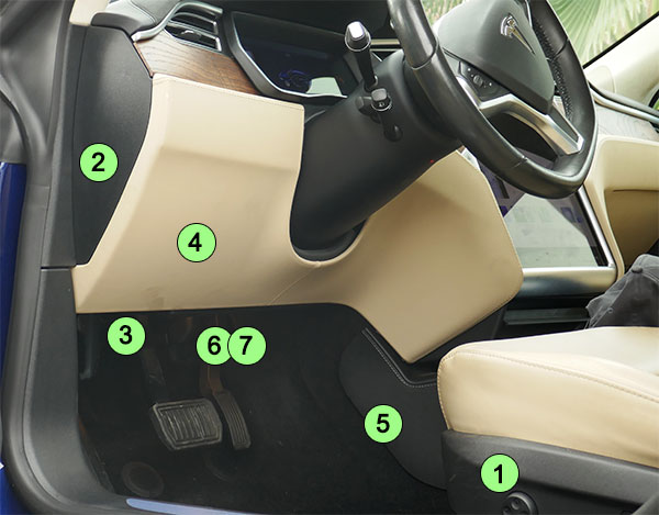
Disassembly steps 1 through 7
- Position the driver’s seat as far back as possible for easier access and remove the carpet mat
- Remove the dash driver’s side panel and disconnect the FOB antenna
- Remove the T20 screw that holds the footwell cover to the under-dash and remove the cover
- Remove the driver’s side padded lower dash trim that is left of the steering wheel, held on by 9 strong snaps
- Ignore this step.
- Remove the two T20 screws near the firewall that hold the under-dash closing trim and partly remove
- Disconnect the footwell lamp mounted to the under-dash closing trim and remove the trim
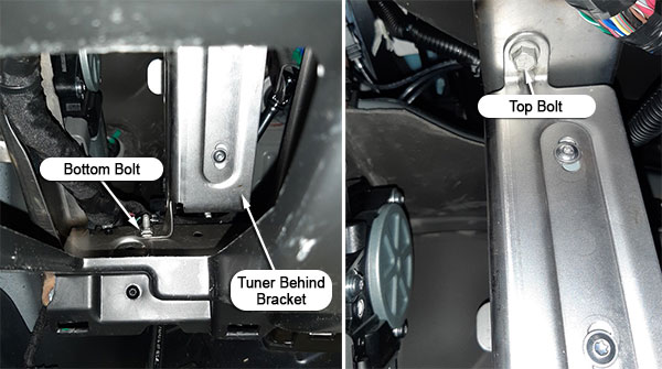
- Remove the two screws holding the ODB-II connector to the tuner bracket
- Remove the connectors attached to the radio module
- Remove the three 10mm bolts holding the retaining bracket

View through the front opening

View looking upwards between tuner and firewall
- Remove the retaining bracket along with the analog radio module
- Remove the 4 screws holding the radio module to the retaining bracket, 2 on each side.
- Replace the radio module.
It may be helpful to see a video on Removing MCU1. It shows some of the steps we outline above as well. Here’s a video on a 2014 Model S that shows the amplifier and radio removal at the 17-minute mark. A refreshed Model S is similar with minor differences.
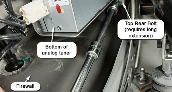
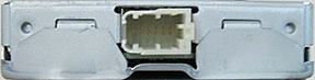
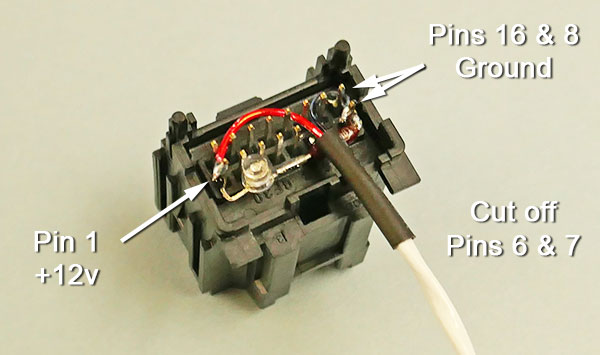
The rear of the analog FM only radio
We will connect to the Tesla analog radio connector to get 12 v power for the new radio. The mating Molex connector is only available in a PCB mount variant. We made a 3D-printed cover to insulate the PCB pins using PTEG. Do not use PLA, as it will deform under high cabin temperatures. As an alternative, perhaps you could use hot melt or perhaps some other means to insulate the back pins once you’ve attached wires for power.

| Pin | Abbreviation | Description | Our Wire Color |
|---|---|---|---|
| 1 | KL15 | 12V via 10 amp fuse | Red |
| 2 | no connection | ||
| 3 | no connection | ||
| 4 | no connection | ||
| 5 | Aux_SHLD | Shield for Line out, Left | |
| 6 | Aux L- | Line out, left, differential, 10KΩ | |
| 7 | Aux L+ | Line out, left, differential, 10KΩ | |
| 8 | KL31 | Ground | Black |
| 9 | no connection | ||
| 10 | CAN+ | CAN 2 data bus, differential | |
| 11 | CAN- | CAN 2 data bus, differential | |
| 12 | no connection | ||
| 13 | Aux_SHLD | Shield for Line out, Right | |
| 14 | Aux R- | Line out, right, differential, 10KΩ | |
| 15 | Aux R+ | Line out, right, differential, 10KΩ | |
| 16 | KL31 | Ground |
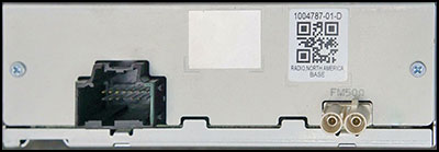
The digital radio is much smaller and is mounted on a bracket that fits into the same spot where the analog radio resided on older cars. It has the same style of antenna connections (shown on the bottom) but a different data connector on the top (purple). There are no AM radio electronics in this module, so there is zero hope for those who want AM radio. The digital radio is made by Harman (now a Samsung company) and manufactured in Mexico. The radio module, not including the bracket, looks very similar to the Model 3 FM radio, which has a third connector to power the antenna amplifier. I suspect a Model 3 radio could be used if you don’t need XM since the connectors appear the same. You would have to fabricate a new bracket. I only mention this, as eBay has some used Model 3 FM radios, but I’ve not seen any Model digital S/X radios for sale on eBay in the last few months.
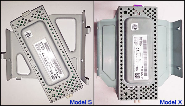
Top view of digital FM radios
Side view of the 10-pin connector for power and data
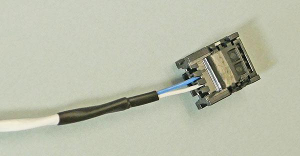
The digital radio connector uses the TE Connectivity 2302475-2 housing and requires five terminals TE Connectivity 2-1703930-1. This connector only has power and ethernet data (4 wires). The way the connector housing works, there are locks on both sides to ensure the terminals do not slide out. Since there is only one terminal in slot 4, on the bottom row, we need to crimp one terminal without a wire and insert it into slot 10, so the housing properly locks. The lock tends to pop open without this extra terminal inserted. Be aware the tiny terminals are difficult to crimp and even more difficult to get into the housing.

| Pin | Abbreviation | Description | Our Wire Color |
|---|---|---|---|
| 1 | PWR | 12V | Red |
| 2 | no connection | ||
| 3 | no connection | ||
| 4 | GRND | Ground | Black |
| 5 | no connection | ||
| 6 | no connection | ||
| 7 | ETH1 | Ethernet | White |
| 8 | no connection | ||
| 9 | ETH2 | Ethernet | Blue |
| 10 | no connection |
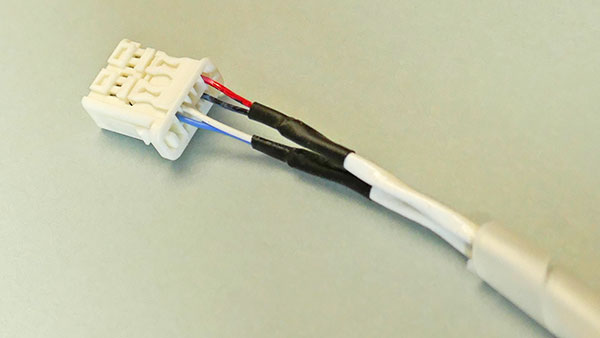
The ethernet connection to MCU2 uses MOLEX 34791-0040. housing and uses two female terminals MOLEX 560023-0550.

| Pin | Abbreviation | Description | Our Wire Color |
|---|---|---|---|
| 1 | no connection | ||
| 2 | ETH1 | Ethernet | White |
| 3 | ETH2 | Ethernet | Blue |
| 4 | no connection |
Cable wiring diagram to add a digital FM/XM radio to MCU2 upgrade. Power is supplied from the old analog radio connector and you can include an optional power-on confirmation LED as part of the analog connector. Some vehicles are not equipped with an XM radio antenna.

Analog radio connector 3D printed cover v8
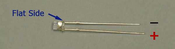
T1 LED polarity
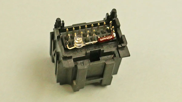
Analog radio connector with LED and resistor
Analog radio connector connected to cable
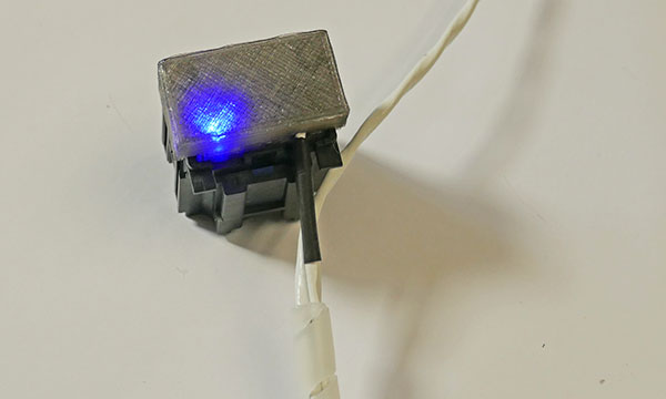
Analog radio connector power test
MCU2 ethernet connector wired
Digital radio connector wired
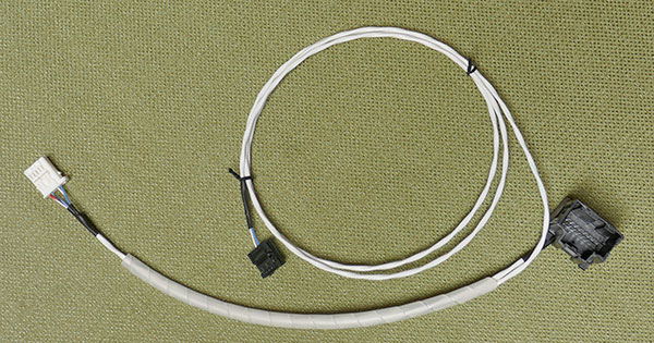
The completed cable assembly
When installing the digital tuner, first connect the two (FM) or three (FM/XM) antenna connections as they may be difficult to get to once installed. On the cable assembly, attach the large 16-pin black connector to the connector that used to go to the analog radio. Use the tie wrap around these connectors and the cover to ensure it will not come apart. Secure the connector so it doesn’t rattle around behind the dash. You may want to warp some felt around the connector as well. The connector back should light up blue if the power is on.
Connect the smaller 10-pin white connector to the bottom of the digital tuner. Run the long white ethernet cable to behind MCU2.
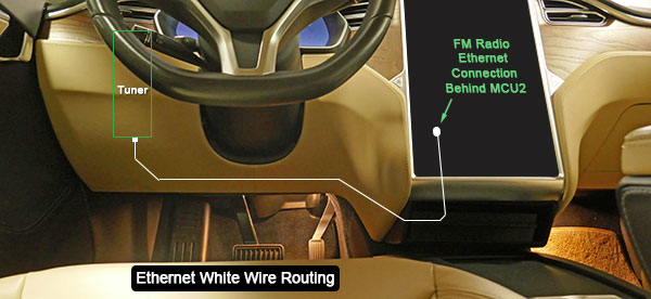
Route of ethernet cable
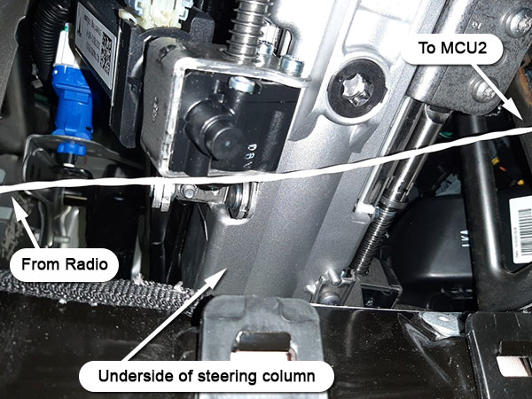
The cable under the steering column
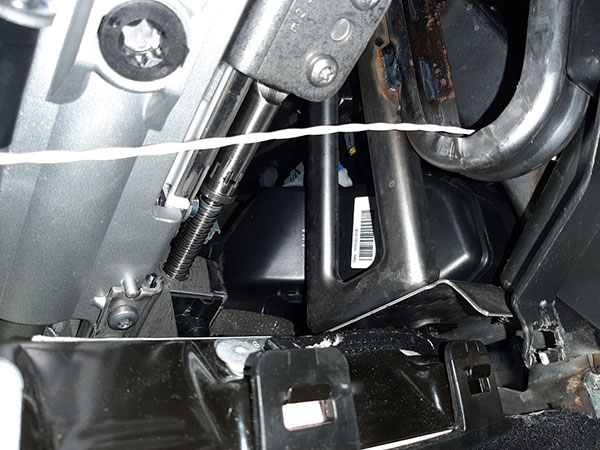
Cable route over to MCU2 via cubby
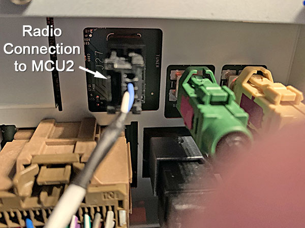
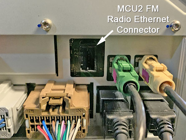
Radio connection to the rear of MCU2
As of this writing, the biggest issue is not the hardware or wiring, but making the car recognize the newly installed digital FM radio. We have confirmed that doing a reset on MCU2, a power-down, or installing a new software version does not activate the radio. It is not like a Windows PC with plug-and-play hardware detection. It needs to be provisioned by Tesla service. Kyle recommends the following approach when you go in for the MCU2 upgrade:
Dear Tesla Technician,
I know that my MCU2 retrofit means that I will lose AM/FM/XM radio because part of the retrofit process does NOT include replacing the old analog tuner that worked with MCU1 with the new digital tuner for MCU2.
I have replaced the tuner myself, and all the wiring is completed. I’ve even routed the FM ethernet cable (white) to the rear of the MCU so you can plug it into MCU2 during the retrofit.
However, MCU2 does not provision the new tuner unless you enable it in the gateway’s internals.dat car configuration. It’s my understanding that all that needs to happen is to change ethernettunertype 1 to ethernettunertype 0 or you could remove that line entirely in the gateway and it’ll start to work.
Would you mind doing this while Toolbox is connected?
Thank you
We have heard that service centers are not allowed to make configuration changes like this. I’d argue that the FM radio is a Tesla part, and MCU2 is designed to be compatible with Tesla’s digital tuner. The car had FM service, so it’s not enabling a feature that didn’t exist previously in the car. Hopefully, if you respectfully do this, and treat the techs right they will do these extra steps for you, but I fear we may need to get corporate to relent before a service center can or will make the change. The more owners that ask for it, the more likely Tesla may accommodate us.
A big thanks go to those who helped with this project and supplied some of the photos, including akikiki, Kyle, Art, as well as a few others!